
Instruction Manual


AR-B1640 User’s Guide
14
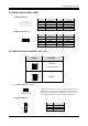
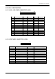
3.11 FLOPPY DRIVE CONNECTOR (FDD1)
The AR-B1640 provides a 34-pin header type connector for supporting up to two floppy disk drives.
To enable or disable the floppy disk controller, please use the BIOS Setup program.
33
34
1
2
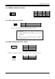
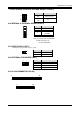
3.12 DOC SOCKET (DOC1)
3.12.1 D.O.C. Memory Bank Address Select (JP2)
This section provides the information about how to use the D.O.C. (Disk On Chip). It divided into two parts:
hardware setting and software configuration.
Step 1:
Use JP2 to select the correct D.O.C. memory bank address.
Step 2:
Insert programmed Disk On Chip into sockets U18 setting as DOC.
Step 3:
Line up and insert the AR-B1640 card into slot of your computer.
JP2
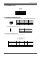
PIN Signal PIN Signal
1-33(odd)
GROUND 18 DIRECTION
2 DRVEN 0 20 -STEP OUTPUT PULSE
4 NOT USED 22 -WRITE DATA
6 DRVEN 1 24 -WRITE GATE
8 -INDEX 26 -TRACK 0
10 -MOTOR ENABLE 0 28 -WRITE PROTECT
12 -DRIVE SELECT 1 30 -READ DATA
14 -DRIVE SELECT 0 32 -SIDE 1 SELECT
16 -MOTOR ENABLE 1 34 DISK CHANGE
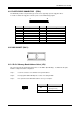
JP2 ADDRESS
ON
D000
(Factory Preset)
OFF D200