AR-B1640 User’s Guide AR-B1640 INDUSTRIAL GRADE CPU BOARD User’ s Guide Edition: 1.01 Book Number: AR-B1640-03.
AR-B1640 User’s Guide Table of Contents 0. PREFACE ………………………………………………………………………………………………………………………3 0.1 COPYRIGHT NOTICE AND DISCLAIMER..................................................................................................................................3 0.2 WELCOME TO THE AR-B1640 CPU BOARD.............................................................................................................................3 0.3 BEFORE YOU USE THIS GUIDE ...................................................
AR-B1640 User’s Guide 0. PREFACE 0.1 COPYRIGHT NOTICE AND DISCLAIMER This document is copyrighted, 2002, by Acrosser Technology Co., Ltd. All rights are reserved. No part of this manual may be reproduced, copied, transcribed, stored in a retrieval system, or translated into any language or computer language in any form or by any means, such as electronic, mechanical, magnetic, optical, chemical, manual or other means without the prior written permission or original manufacturer.
AR-B1640 User’s Guide 0.6 STATIC ELECTRICITY PRECAUTIONS Before removing the board from its anti-static bag, read this section about static electricity precautions. Static electricity is a constant danger to computer systems. The charge that can build up in your body may be more than sufficient to damage integrated circuits on any PC board. It is, therefore, important to observe basic precautions whenever you use or handle computer components.
AR-B1640 User’s Guide 1. INTRODUCTION Welcome to the AR-B1640 PCI Single Board Computer. The AR-B1640 board is PIC form factor board, which comes equipped with high performance VIA ® Eden or C3 Processor with the VIA ® advanced chipset Apollo PLE133T (VT8601T and VT82C686B). This product is designed for the system manufacturers, integrators, or VARs that want to provide all the performance, reliability, and quality at a reasonable price. In addition, the AR-B1640 provides on chip VGA.
AR-B1640 User’s Guide 1.
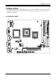
AR-B1640 User’s Guide 2. INSTALLATION This chapter describes how to install the AR-B1640. At first, the layout of AR-B1640 is shown, and the unpacking information that you should be careful is described. The following lists the jumpers and switches setting for the AR-B1640’s configuration. 2.
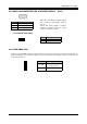
AR-B1640 User’s Guide 2.2 POWER ON CONNECTOR FOR ATX POWER SUPPLY (ATX1) 1 2 PIN 1 2 3 3 * When AT power supplier is applied, jumper 2&3 should be tied together. (Factory preset) * When ATX power supplier is applied, pin1&pin 3 should be connect to proper location of ATX power supplier. Signal PSON VCC 5VSB • ATX POWER BUTTON (BTON1) 1 Pin 1 2 2 Signal -PWBN GND 2.
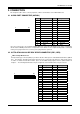
AR-B1640 User’s Guide 3. CONNECTION This chapter describes how to connect peripherals, switches and indicators to the AR-B1640 board. 3.
AR-B1640 User’s Guide • IDE 2: Second IDE Connector AR-B1640 also provides IDE interface 44-pin connector to connect with the hard disk device.
AR-B1640 User’s Guide 3.4 SERIAL PORTS (COM1, COM2) • COM1 D-SUB 9-PIN 1 6 5 9 PIN 1 3 5 7 9 Signal /DCD1 TXD1 GND /RTS1 /RI1 PIN 1 3 5 7 9 Signal /DCD2 RXD2 TXD2 /DTR2 GND PIN 2 4 6 8 10 Signal RXD1 /DTR1 /DSR1 /CTS1 GND • COM2 10-pin Connector 9 1 10 2 PIN 2 4 6 8 10 Signal /DSR2 /RTS2 /CTS2 /RI2 NC 3.
AR-B1640 User’s Guide 3.5 KEYBOARD / MOUSE CONNECTOR (PS1, PS2) The AR-B1640 provides 6-PIN JST Header and 6-PIN MINI-DIN keyboard/mouse connector. • PS1: 6-pin Mini-DIN Keyboard/Mouse Connector 1 2 3 4 5 6 Front View PIN 1 2 3 4 5 6 Signal KBDATA MSDATA GND VCC MSCLK KBCLK PIN 1 2 3 4 5 6 Signal MSDATA KBDATA GND VCC MSCLK KBCLK • PS2: JST6-pin Keyboard/Mouse Connector 1 6 PS2 3.6 USB PORT CONNECTOR (USB1) The AR-B1640 provides Two USB port.
AR-B1640 User’s Guide 3.8 FAN CONNECTOR (FAN1) The AR-B1640 provides CPU cooling Fan connector. CPU connectors can supply 12V/500mA to the cooling fan. 3 2 1 PIN 1 2 3 Signal GND +12V SENSE 3.9 ETHERNET RJ45 CONNECTOR (LAN1) The Ethernet RJ-45 connectors are the standard network headers. 8 1 Pin 1 2 3 4 The following table is the pin assignment.
AR-B1640 User’s Guide 3.11 FLOPPY DRIVE CONNECTOR (FDD1) The AR-B1640 provides a 34-pin header type connector for supporting up to two floppy disk drives. To enable or disable the floppy disk controller, please use the BIOS Setup program.
AR-B1640 User’s Guide 3.13 GENERAL PURPOSE I/O (GPIO1) 7 1 8 2 Pin 1 3 5 7 Signal GPI0 GPI1 GPI2 GPI3 Pin 2 4 6 8 Signal GPO0 GPO1 GPO2 GPO3 3.13.1 GPIO Address Select (JP3) JP3 ON OFF JP3 ADDRESS 215H (Factory Preset) 77H # Users could test GPIO function under ‘Debug’ program as follow: # # C:>debug O 215 01H Generally, the GPIO2 Pin2 will be High Level, others output pin are Low Level. I 215 FC Generally, suppose that GPIO1’s Pin1 and Pin3 are High Level then will show “FC” 3.
AR-B1640 User’s Guide 3.15 LCD & LVDS FUNCTION 3.15.1 18-Bits LCD PANEL CONNECTOR (LCD1) PIN 1 2 3 4 5 6 7 8 9 10 11 12 13 14 15 2 44 1 43 Signal GND SFCLK GND HSYNC VSYNC GND (PD22) (PD23) B0 B1 B2 B3 GND B4 B5 PIN 16 17 18 19 20 21 22 23 24 25 26 27 28 29 30 Signal (PD18) (PD19) G0 G1 GND G2 G3 G4 G5 (PD21) (PD20) GND R0 R1 R2 PIN 31 32 33 34 35 36 37 38 39 40 41 42 43 44 Signal R3 R4 R5 GND LCDVCC LCDVCC +12V +12V GND GND DE EBLT GND EVEE 3.15.
AR-B1640 User’s Guide 3.15.3 LVDSVCC & LCDVCC VOLTAGE SELECT (LVDSV1) 1 2 5 6 LVDSV1 1-3 2-4 ON 3-5 4-6 ON VOLTAGE +3.3V (Factory Preset) +5V 3.16 INTERNAL & EXTERNAL BUZZER (ESPK1) PIN 1 2 1 Signal VCC SBEEP INTERNAL BUZZER SBEEP 3 4 4 PIN 1,2: Connect to External BUZZER 3-4 ON (Factory Preset) Use Internal BUZZER 3.17 RESET SWITCH (RST1) Shorting these two pins will reset the system. 2 PIN 1 2 1 Signal RST GND 3.
AR-B1640 User’s Guide 4. WATCHDOG TIMER This section describes the use of Watchdog Timer, including disable, enable, and trigger. AR-B1640 is equipped with a programmable time-out period watchdog timer that occupies I/O port 443H. Users can use simple program to enable the watchdog timer. Once you enable the watchdog timer, the program should trigger it every time before it times out.
AR-B1640 User’s Guide 5. BIOS CONSOLE This chapter describes the AR-B1640 BIOS menu displays and explains how to perform common tasks needed to get up and running, and presents detailed explanations of the elements found in each of the BIOS menus.
AR-B1640 User’s Guide 5.2 STANDARD CMOS SETUP The option allows you to record some basic system hardware configuration and set the system clock and error handling. If the CPU board is already installed in a working system, you will not need to select this option anymore. Standard CMOS Setup Date & Time Setup Highlight the field and then press the [Page Up] /[Page Down] or [+]/[-] keys to set the current date. Follow the month, day and year format.
AR-B1640 User’s Guide 5.3 ADVANCED CMOS SETUP The option consists of configuration entries that allow you to improve your system performance, or let you set up some system features according to your preference. Some entries here are required by the CPU board’s design to remain in their default settings. Advanced CMOS Setup Quick Boot This category speeds up Power On Self Test (POST) after you power on the computer. BIOS will shorten or skip some check items during POST.
AR-B1640 User’s Guide PS/2 Mouse Support The setting of Enabled allows the system to detect a PS/2 mouse on boot up. If detected, IRQ12 will be used for the PS/2 mouse. IRQ 12 will be reserved for expansion cards if a PS/2 mouse is not detected. Disabled will reserve IRQ12 for expansion cards and therefore the PS/2 mouse will not function. Primary Display The option is used to set the type of video display card installed in the system.
AR-B1640 User’s Guide 5.4 ADVANCED CHIPSET SETUP This option controls the configuration of the board’s chipset. Control keys for this screen are the same as for the previous screen. Advanced Chipset Setup Configure SDRAM Timing by SPD SPD is the abbreviation Serial Presence Detect. SPD takes accord the chip types, capacity, timing, voltage data. The system can auto adjust memory according to the data to reach the best situation.
AR-B1640 User’s Guide 5.5 POWER MANAGEMENT This section is used to configure power management features. This option allows you to reduce power consumption. This feature turns off the video display and shuts down the hard disk after a period of inactivity. Power Management ACPI Aware O/S The option YES is for ATX power, the option NO is for AT Power.
AR-B1640 User’s Guide 5.6 PCI/PLUG AND PLAY This section is used to configure PCI / Plug and Play features. bus slots. The option configures the PCI PCI / Plug And Play Plug and Play Aware O/S Set this option to Yes if the operating system installed in the computer is Plug and Play-aware. The BIOS only detects and enables PnP ISA adapter cards that are required for system boot. The Windows 95 operating system detects and enables all other PnP-aware adapter cards.
AR-B1640 User’s Guide 5.7 PERIPHERAL SETUP This section is used to configure peripheral features. Peripheral Setup OnBoard FDC This option enables the floppy drive controller on the AR-B1640. OnBoard Serial Port This option enables the serial port on the AR-B1640. IR Port support This item is to activate the function of Infrared. OnBoard Parallel Port This option enables the parallel port on the AR-B1640. Parallel Port Mode This option specifies the parallel port mode.
AR-B1640 User’s Guide 5.8 AUTO-DETECT HARD DISKS This option detects the parameters of an IDE hard disk drive, and automatically enters them into the Standard CMOS Setup screen. 5.9 PASSWORD SETTING This BIOS Setup has an optional password feature. The system can be configured so that all users must enter a password every time the system boots or when BIOS Setup is executed. User can set either a Supervisor password or a User password.
AR-B1640 User’s Guide 5.12 BIOS UPDATE The BIOS program instructions are contained within computer chips called FLASH ROMs that are located on your system board. The chips can be electronically reprogrammed, allowing you to upgrade your BIOS firmware without removing and installing chips. The AR-B1640 provides the FLASH BIOS update function for you to easily to update to a newer BIOS version.
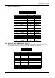
AR-B1640 User’s Guide APPENDIX A. ADDRESS MAPPING IO Address Map I/O MAP 000-01F 020-021 022-023 040-05F 060-06F 070-07F 080-09F 0A0-0BF 0C0-0DF 0F0-0FF 1F0-1F8 250-258 2B0-2DF 2F8-2FF 360-36F 378-37F 3B0-3BF 3C0-3CF 3D0-3DF 3F0-3F7 3F8-3FF ASSIGNMENT DMA controller (Master) Interrupt controller (Master) Chipset controller registers I/O ports. Timer control registers.
AR-B1640 User’s Guide APPENDIX B.