
User guide

AR-B1640 User’s Guide
15
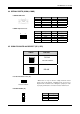
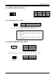
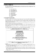
3.13 GENERAL PURPOSE I/O (GPIO1)
7
1
8 2
3.13.1 GPIO Address Select (JP3)
JP3
# Users could test GPIO function under ‘Debug’ program as follow:
C:>debug
# O 215 01H
Generally, the GPIO2 Pin2 will be High Level, others output pin
are Low Level.
# I 215
FC
Generally, suppose that GPIO1’s Pin1 and Pin3 are High Level
then will show “FC”
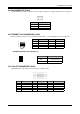
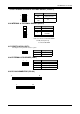
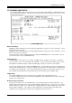
3.14 POWER CONNECTOR (PWR1, PWR2)
1 4
(PWR1)
The PWR1 is a 4-pin power connector. It’s the standard connectors on all Acrosser boards.
1 2
(PWR2)
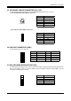
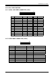
Pin Signal Pin Signal
1 GPI0 2 GPO0
3 GPI1 4 GPO1
5 GPI2 6 GPO2
7 GPI3 8 GPO3
JP3 ADDRESS
ON 215H (Factory Preset)
OFF 77H
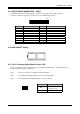
PIN Signal
1 +12V
2 GND
3 GND
4 VCC (+5V)
PIN Signal
1 -12V
2 -5V