
User guide

AR-B1640 User’s Guide
9
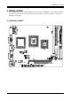
3. CONNECTION
This chapter describes how to connect peripherals, switches and indicators to the AR-B1640 board.
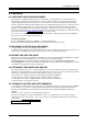
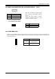
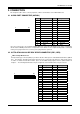
3.1 AUDIO PORT CONNECTOR (AUDIO1)
25
26
1
2
Note: the connector does not contain the GAME (MIDI) port signal. When AR-B9425 audio card is used with this
CPU board, the GAME port function is not supported. If users want to use the amplified trumpet that is constructed
inside, please plug it into the line out. If not, please plug it into the speak-out.
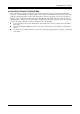
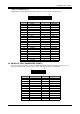
3.2 ULTRA ATA33/66/100 IDE DISK DRIVE CONNECTOR (IDE1, IDE2)
•
IDE1: Primary IDE Connector
A 40-pin header type connector (IDE1) is provided to interface with up to two embedded hard disk drives (IDE AT
bus). This interface, through a 40-pin cable, allows the user to connect up to two drives in a “daisy chain” fashion.
To enable or disable the hard disk controller, please use the BIOS Setup program, which is explained further in
chapter 5. The following table illustrates the pin assignments of the hard disk drive’s 40-pin connector.
1 39
2 40
Pin Signal Pin Signal
1 AUXAL 2 LINEL
3 AUXAR 4 LINER
5 +12V 6 +5V
7 AUDIOL 8 MICPH
9 AUDIOR 10 PCSPKO
11 GND 12 GND
13 Not Used 14 Not Used
15 GND 16 GND
17 Not Used 18 Not Used
19 Not Used 20 Not Used
21 Not Used 22 Not Used
23 Not Used 24 Not Used
25 GND 26 GND
Pin Signal Pin Signal
1 -RESET 2 GROUND
3 DATA 7 4 DATA 8
5 DATA 6 6 DATA 9
7 DATA 5 8 DATA 10
9 DATA 4 10 DATA 11
11 DATA 3 12 DATA 12
13 DATA 2 14 DATA 13
15 DATA 1 16 DATA 14
17 DATA 0 18 DATA 15
19 GROUND 20 N.C
21 PDDREQ 22 GROUND
23 -PDIOW 24 GROUND
25 -PDIOR 26 GROUND
27 PIORDY 28 GROUND
29 -PDDACK 30 GROUND
31 IRQ14 32 N.C
33 PDA1 34 PD66/100
35 PDA0 36 PDA2
37 -PDCS1 38 -PDCS3
39 HLEDP 40 GROUND