
Instruction Manual


14
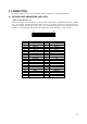
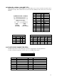
3.6 USB CONNECTOR (USB1, USB2, USB3)
1 2 3 4
5 6 7 8 1.VCC
2.DATA0+
3.DATA0-
4.GND
5.VCC
6.DATA1+
7.DATA1-
8.GND
USB1&USB2
USB 3
1 9
2 10
1.VCC 6.DATA3+
2.GND 7.GND
3.DATA2- 8.DATA3-
4.GND 9.GND
5.DATA2+ 10.VCC
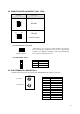
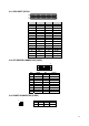
3.7 FAN POWER CONNECTOR
The AR-B1790 provides CPU cooling Fan connector. CPU connectors can supply 12V/500mA to the cooling fan.
3 2 1
FAN1 FOR CPU FAN
FAN2 FOR SYSTEM FAN
FAN3 FOR CASE FAN
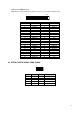
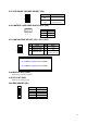
3.8 DUAL ETHERNET PORT (PT3)
The Ethernet RJ-45 connectors are the standard network headers. The following table is the pin assignment.
PIN Signal
1 GND
2 +12V
3 SENSE
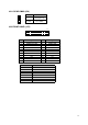
Pin Signal Pin Signal
1 TX+ 5 Not Used
2 TX- 6 RX-
3 RX+ 7 Not Used
4 Not Used 8 Not Used
18