AR-B1893 User’s Guide AR-B1893 Pentium M inside, On Board VGA with On Board DDR and SO DIMM, 4 Port built in LAN, 1 Mini PCI, 1 CF Edition: 1.0 Book Number: AR-B1893-2005.07.
AR-B1893 User’s Guide @Copyright 2005 All Rights Reserved. Manual first edition July 8, 2005 The information in this document is subject to change without prior notice in order to improve reliability, design and function and does not represent a commitment on the part of the manufacturer.
AR-B1893 User’s Guide Contents Contents ............................................................... 3 Introduction............................................................ 5 1.1 Specifications: ........................................................................... 5 1.2 What You Have ......................................................................... 6 Installation ............................................................. 7 2.1 AR-B1893’s Layout.......................................
AR-B1893 User’s Guide 3.8 PCI Slot ................................................................................ 18 3.9 Mini PCI Slot ............................................................................ 18 3.10 DDR SODIMM Socket ........................................................... 18 3.11 GPIO ..................................................................................... 19 3.12 Internal Buzzer....................................................................... 19 3.
AR-B1893 User’s Guide 1 Introduction 1.1 Specifications: • CPU : Pentium M or Celeron M • Chipset : GMCH 852GM and ICH4 82810DB • RAM memory : On Board DDR up to 256MB/266MHz & 1 DDR SODIMM Socket up to 1 GB/266MHz. • Ultra DMA 133 IDE Interface : Two PCI Enhance IDE channel. • CompactFlash interface : Supports CompactFlash socket for Compact Flash Disk or IBM Micro Drive. • Series ports : Two high-speed 16C550 compatible UARTs ports • USB port : Support four USB 2.0 compatible ports.
AR-B1893 User’s Guide 1.
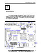
AR-B1893 User’s Guide 2 Installation This chapter describes how to install the AR-B1893. At first, the layout of AR-B1893 is shown, and the unpacking information that you should be careful is described. The jumpers and switches setting for the AR-B1893’s configuration 2.
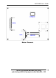
AR-B1893 User’s Guide Bottom Placement AR-B11893 Pentium M inside (With VGA) with On Board DDR, 4 Port built in LAN, 1 Mini PCI, 1 CF 8
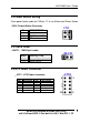
AR-B1893 User’s Guide 2.2 Power Button Setting Place power button cable on CN3 pin 1-2 & use Mechanical Power Button. • CN3 : Power Button Connector Pin 1–2 3 4 DESCRIPTION Power Button 12 V Button LED NC CN3 3 1 4 2 2.3 CMOS Reset • JBAT1 : CMOS pin header JBAT1 JBAT1 1-2 2-3 DESCRIPTION Normal Operation Reset CMOS 1 2 3 2.
AR-B1893 User’s Guide 2.
AR-B1893 User’s Guide 3 Connection This chapter describes how to connect peripherals, switches and indicators to the AR-B1893 board. 3.1 Ultra ATA33/66/100 IDE Disk Drive Connector You can attach two IDE( Integrated Device Electronics) hard disk drives to the AR-B1893 IDE controller. IDE 1 : Primary IDE Connector (40 Pins) PIN NO.
AR-B1893 User’s Guide IDE 2 : Secondary IDE Connector (44 Pins) PIN NO. 1 3 5 7 9 11 13 15 17 19 21 23 25 27 29 31 33 35 37 39 41 43 3.2 DESCRIPTION RESET# DATA 7 DATA 6 DATA 5 DATA 4 DATA 3 DATA 2 DATA 1 DATA 0 GROUND N/C IOW# IOR# N/C N/C INTERRUPT SA1 SA0 HDC CS0# HDD ACTIVE# +5V LOGIC GROUND PIN NO.
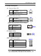
AR-B1893 User’s Guide • COM1 : DB-9 Male PIN NO. 1 2 3 4 5 6 7 8 9 DESCRIPTION DATA CARRIER DETECT RECEIVE DATA TRANSMIT DATA DATA TERMINAL READY GROUND DATA SET READY REQUEST TO SEND CLEAR TO SEND RING INDICATOR (DCD) (RXD) (TXD) (DTR) (DSR) (RTS) (CTS) (RI) • COM2 : 10-pin Connector PIN NO.
AR-B1893 User’s Guide 3.3 Keyboard / Mouse Connector The AR-B1893 provides PS/2 Mouse & Keyboard Connector. • PS1 : 6-pin Mini-DIN Keyboard/Mouse Connector PIN NO. 1 2 3 4 5 6 DESCRIPTION MOUSE DATA KEYBOARD DATA GROUND +5V MOUSE CLOCK KEYBOARD CLOCK 1 6 3.4 USB Port Connector The AR-B1893 provides four USB port, port 0, port 1, port 3 and port 4 . USB1 Port (Port 0 & Port 1) : 1. VCC 2. USB03. USB0+ 4. GROUND 5. VCC 6. USB17. USB18. GROUND 1 4 5 8 USB3 Pin Header (Port 3 & Port 4) : 1. VCC 2 2.
AR-B1893 User’s Guide 3.5 Fan Connector The AR-B1893 provides 3 connectors for CPU cooling fan & system fan & they can be controlled by Super I/O Chip. • CPUF1, CPUF2 & CPUF3: Fan Connector for CPU & System PIN NO. 1 2 3 DESCRIPTION Sense 1 2 3 12 V Ground 3.6 LAN RJ45 Connector AR-B1893 is equipped with built-in 2 x 10/100Mbps and 2 x 10/100/1000Mbps Ethernet Controller. You can connect it to your LAN through RJ45 LAN connector.
AR-B1893 User’s Guide • LED1, LED2 LED3 and LED4 : LAN LED COLOR DESCRIPTION Red Green Yellow LED 1 2 3 4 100MBps 1000MBps Action DESCRIPTION For LAN 1 For LAN 2 For LAN 3 For LAN 4 R G Y • VGA1 : 10-pin Connector PIN NO. 1 2 3 4 5 6 7 8 9 10 3.7 DESCRIPTION RED ( R ) GROUND GREEN (G) GROUND BLUE (B) GROUND VERTICAL SYNCHRON (VS) CLOCK (CLK) HORIZONTAL SYNCHRON (HS) DATA (SDATA) 2 10 1 9 Compact Flash Storage Card Socket The AR-B1893 configures Compact Flash Storage Card in IDE Mode.
AR-B1893 User’s Guide •CFD1 : Compact Flash Storage Card Socket pin assignment PIN NO. 1 2 3 4 5 6 7 8 9 10 11 12 13 14 15 16 17 18 19 20 21 22 23 24 25 DESCRIPTION GROUND D3 D4 D5 D6 D7 CS1# N/C GROUND N/C N/C N/C VCC N/C N/C N/C N/C A2 A1 A0 D0 D1 D2 N/C CARD DETECT2 PIN NO.
AR-B1893 User’s Guide 3.8 PCI Slot • PCI1 A1 A62 B1 B62 3.9 Mini PCI Slot • MPCI1 2 124 1 123 3.
AR-B1893 User’s Guide 3.11 GPIO • CN2 PIN NO. 1 2 3 4 5 DESCRIPTION GPIO1 GPIO5 GPIO2 GPIO6 GPIO3 PIN NO. 6 7 8 9 10 DESCRIPTION GPIO7 GPIO4 GPIO8 GROUND VCC 9 1 10 2 3.12 Internal Buzzer • BZ1 3.13 Power / HD / Watchdog LED • LED5 COLOR Red Green Yellow DESCRIPTION Hard Disk Active Power OK Watch Dog Bypass Timeout R G Y 3.
AR-B1893 User’s Guide 3.15 ISP CPLD Connector • CN1 PIN NO.
AR-B1893 User’s Guide 4 Award BIOS Setup 4.1 Introduction This chapter discusses the Setup program built into the BIOS. The Setup program allows users to configure the system. This configuration is then stored in battery-backed CMOS RAM so that it retains the Setup information while the power is off. 4.2 Starting Setup The BIOS is immediately active when you turn on the computer. While the BIOS is in control, the Setup program can be activated in one of two ways: 1.
AR-B1893 User’s Guide 4.3 Using Setup In general, you can use the arrow keys to highlight items, press to select, use the PageUp and PageDown keys to change entries, press for help and press to quit. The following table provides more details about how to navigate in the Setup program using the keyboard.
AR-B1893 User’s Guide 4.4 Main Menu The items in Standard CMOS Setup Menu are divided into 10 categories. Each category includes no, one or more than one setup items. Use the arrow keys to highlight the item and then use the or keys to select the value you want in each item.
AR-B1893 User’s Guide IDE Primary Slave Base Memory Options are in its sub menu (described in Table 3) Options are in its sub menu (described in Table 3) Options are in its sub menu (described in Table 3) None 360K, 5.25 in 1.2M, 5.25 in 1.720K, 3.5 in 1.44K, 3.5 in 2.88K, 3.
AR-B1893 User’s Guide IDE HDD Auto-Detection[Press Enter] IDE Primary Master [Auto] Access Mode [Auto] Capacity 0MB Cylinder 0 Head 0 Precomp 0 Landing Zone 0 Sector 0 Figure 2 IDE Primary Master sub menu Use the legend keys to navigate through this menu and exit to the main menu. Use Table 2 to configure the hard disk.
AR-B1893 User’s Guide Access Mode CHS LBA Large Auto disk checking program. Choose the access mode for this hard disk Table 2 Hard disk selections 4.5 Advanced BIOS Features This section allows you to configure your system for basic operation.
AR-B1893 User’s Guide Power Supply Type [AT] Power On After Power Fail [Off] Figure 3 Advanced menu Quick Power On Self Test This category speeds up Power On Self Test (POST) after you power up the computer. If it is set to Enable, BIOS will shorten or skip some check items during POST. Enabled Enable quick POST Disabled Normal POST Full Screen LOGO Show This item allows you to enable or disable show full screen LOGO. The Choice: Enabled, Disabled.
AR-B1893 User’s Guide USB Keyboard Support This item allows you to enable or disable USB keyboard support. The Choice: Enabled, Disabled. Init Display First This item allows you to choose which Display to be first detected. The Choice: PCI Slot, On Board / AGP. Boot Display This item allows you to choose display interface. The Choice: Vbios default, CRT, EFP, TV, CRT + EFP, CRT + TV. On-Chip Frame Buffer Size This item allows you to Choose the Frame Buffer size for Display.
AR-B1893 User’s Guide 4.6 PnP/PCI Configuration Setup Reset Configuration Data[Disabled] Resources Controlled By[Auto(ESCD)] x IRQ Resources Figure 4 PnP/PCI menu Resource controlled by The Award Plug and Play BIOS has the capacity to automatically configure all of the boot and Plug and Play compatible devices. However, this capability means absolutely nothing unless you are using a Plug and Play operating system such as Windows95.
AR-B1893 User’s Guide 4.7 Peripheral Onboard Serial Port 1 [3F8/IRQ4] Onboard Serial Port 2 [2F8/IRQ3] UART Mode Select [Normal] On Board Parallel Port [3BC/IRQ7] Parallel Port Mode SPP USB Controller [Enabled] USB 2.0 Controller [Enable] Figure 5 Peripheral menu Onboard Serial Port 1/Port 2 Select an address and corresponding interrupt for the first and second serial ports. The choice: 3F8/IRQ4, 2E8/IRQ3, 3E8/IRQ4, 2F8/IRQ3, Disabled, Auto UART Mode Select Select the Function Mode for UART.
AR-B1893 User’s Guide USB Controller Select Enabled if your system contains a Universal Serial Bus (USB) controller and you have USB peripherals. The Choice: Enabled, Disabled. USB 2.0 Controller This Entry is for disable / enable EHCI controller only. The Bios itself may / may not have high speed USB support. If the Bios has high speed USB support built in, the support will be automatically turn on when high speed device were attached. The Choice: Enabled, Disabled. 4.8 PC Health CPU Warning Temp.
AR-B1893 User’s Guide CPU Warning Temp This item allows you to enable or disable the agent after boot. The Choice: Enabled, Disabled. Shutdown Temperature This item allows the system to reset when temperature reach the trigger level. The Choice: Disabled, 60°C/140°F, 65°C/149°F, 70°C/158°F, 75°C/167 °F 4.
AR-B1893 User’s Guide Ø Ø Ø Ø Ø Ø Ø CDROM … … … .[ ] ZIP100 … … … .[ ] USB-FDD ..… ...[ ] USB-ZIP ..… ...[ ] USB-CDROM ..[? ] On Board LAN … [ ] Disabled … ..… … [ ] On Board LAN Boot Select Select through which LAN Channel should the system boot.
AR-B1893 User’s Guide 4.10 Exit Selecting Ø Ø Ø Ø Save & Exit Setup Load Optimized Defaults Exit Without Saving Load Fail-Save Default Figure 8 Exit menu Save & Exit Setup Pressing on this item asks for confirmation: Save to CMOS and EXIT (Y/N)? Y Pressing “Y” stores the selections made in the menus in CMOS – a special section of memory that stays on after you turn your system off.
AR-B1893 User’s Guide Exit Without Saving Pressing on this item asks for confirmation: Quit without saving (Y/N)? Y This allows you to exit Setup without storing in CMOS any change. The previous selections remain in effect. This exits the Setup utility and restarts your computer. Load Fail-Safe Defaults Use this menu to load the BIOS default values that are factory settings for safety system operations.