
Instruction Manual

AR-B1893 User’s Guide
AR-B11893 Pentium M inside (With VGA)
with On Board DDR, 4 Port built in LAN, 1 Mini PCI, 1 CF
9
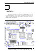
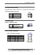
2.2 Power Button Setting
Place power button cable on CN3 pin 1-2 & use Mechanical Power Button.
•
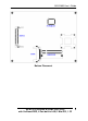
CN3 : Power Button Connector
Pin DESCRIPTION
1 – 2
Power Button
3 12 V Button LED
4 NC
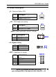
2.3 CMOS Reset
•
JBAT1 : CMOS pin header
JBAT1
DESCRIPTION
1-2 Normal Operation
2-3 Reset CMOS
2.4 ATX Power Connector
•
ATX1 : ATX Power connector
PIN
Description
PIN
Description
1 PS-ON 6 5V
2 5VSB 7 +12V
3 GND 8 -12V
4 5V 9 NC
5 GND 10 GND
CN3
2
1
4
3
JBAT1
2
1
3
ATX1
1
5
6
10