Revision: 1.0 AR-B5631 Board Socket P Intel® Core™2 Duo EPIC SBC with Intel® GME965 Express Chipset, DVI/LCD, Singal LAN and PCI-104 Eexpansion User Manual Manual Rev.: 1.01 Book Number: AR-B5631-2010.07.
Revision: 1.0 Revision Version 1.0 1.
Revision: 1.0 Copyright 2010 All Rights Reserved. Manual’s first edition: June 7, 2010 For the purpose of improving reliability, design and function, the information in this document is subject to change without prior notice and does not represent a commitment on the part of the manufacturer.
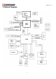
Revision: 1.0 Table of Contents 1 Introduction .......................................................................................... 5 1.1 Features .......................................................................................................... 5 1.2 Package Contents .......................................................................................... 7 1.3 Block Diagram ................................................................................................
Revision: 1.0 1 INTRODUCTION Welcome to the AR-B5631 Computer. The AR-B5631 is an Intel Core 2 Duo EPIC single board computer provides variety of display outputs. In addition to VGA, DVI and LVDS display outputs, AR-B5632 supports S-Video, BNC, and component TV outputs. 1.
Revision: 1.0 Watchdog Timer 256Levels (1~255 +/- 5%sec) CPU Voltage Hardware CPU Temperature Monitoring Fan Speed Voltage Monitor (12V, 5V, 3.
Revision: 1.0 1.2 Package Contents Check if the following items are included in the package.
Revision: 1.0 1.
Revision: 1.0 2 H/W INFORMATION This chapter describes the installation of AR-B5631. At first, it shows the Function diagram and the layout of AR-B5631. It then describes the unpacking information which you should read carefully, as well as the jumper/switch settings for the AR-B5631 configuration. 2.1 Locations 2.1.
Revision: 1.0 2.1.
Revision: 1.0 2.1.3 List of Connector and Jumper Setting PWR2 External +12V DC power input connector. USB3 Internal USB4, USB5 connector. COM2* RS-232/422/485 signal connector for port #2. CON2 ATX function connector. USB2 Internal USB2, USB3 connector. GPIO1 8-bit TTL-5V GPIO connector. CON3 Extra +12V and +5V DC power output connector (for SATA device). USB1 External USB0, USB1 connector. AUDIO1 2 channels Audio signal connector. J10 PCI-104 connector.
Revision: 1.0 2.2 Connector and Jumper Setting Table 1. PWR2: External +12V DC power input connector. PIN 1 2 3 4 SETTING GND GND +12V +12V 4. J10: PCI-104 connector. 2. CON2: ATX function connector. PIN 1 2 3 SETTING GND PS_ON +5V_SUS 5. JP2: Signal SERIRQ connects to PCI-104 pin #B2 selection. STATUS PCI-104 connector. Open Short 7. BAT1: CMOS battery holder. CMOS battery holder. PIN 1 2 3 4 STATUS Connected. Short SATA device connector #2. SETTING +12V GND +3.3V +5V 6.
Revision: 1.0 10. J8: CF master or slave select. 11. IDE1: PATA connector. PIN SIGNAL PIN SIGNAL 1 RESET 2 GND 3 D7 4 D8 5 D6 6 D9 7 D5 8 D10 9 D4 10 D11 11 D3 12 D12 13 D2 14 D13 15 D1 16 D14 17 D0 18 D15 GND 20 NC STATUS SIGNAL 19 SHORT MASTER 21 DREQ 22 GND SLAVE(Default) 23 IOW# 24 GND 25 IOR# 26 GND 27 IORDY 28 GND 29 DACK# 30 GND 31 IDEIRQ 32 NC 33 A1 34 PDIAG OPEN 12. J12: Front panel connector.
Revision: 1.0 14. USB2: Internal USB2, USB3 connector. 15. USB1: External USB0, USB1 connector. PIN SIGNAL PIN SIGNAL 1 +5V 2 +5V 3 USB_3- 4 USB_2- 5 USB_3+ 6 USB_2+ 7 GND 8 GND 9 GND 10 GND 16. LAN1: RJ45 connector for Gigabit Ethernet port #1. PIN SIGNAL PIN SIGNAL 1 +5V 5 +5V 2 USB_1- 6 USB_0- 3 USB_1+ 7 USB_0+ 4 GND 8 GND 17. DVI1: Digital Video Interface (DVI-D). PIN SIGNAL PIN SIGNAL 1 TD2- (Digital red-) 13 N.
Revision: 1.0 18. LCD1: LCD panel (LVDS, 18-bit/36-bit) connector. PIN 1 3 5 7 9 11 13 15 17 19 21 23 25 27 29 SETTING LCD VDD E CLKGND E Data2+ E Data1NC E Data0+ GND O CLKO Data2+ I2C CLK O Data1O Data0+ NC LCD VDD PIN 2 4 6 8 10 12 14 16 18 20 22 24 26 28 30 19. LCDPW1: LCD panel inverter power connector. SETTING GND E CLK+ E Data2GND E Data1+ NC E Data0O CLK+ GND O Data2O Data1+ I2C Data O Data0NC LCD VDD PIN 1 2 3 4 5 6 SETTING +12V +12V GND BKL ON GND Reserved. E: Even for dual channel.
Revision: 1.0 24. COM1*: RS232 signal connector for port 25. COM2*: RS-232/422/485 signal connector #1. for port #2. PIN RS-232 RS-422 RS-485 D-SUB-9 male connector for RS232 port #1. 26. GPIO1:8-bit TTL-5V GPIO connector. 1 DCD N.C N.C 2 DSR RX- N.C 3 RX RX+ N.C 4 RTS N.C N.C 5 TX N.C N.C 6 CTS TX- DATA- 7 DTR N.C N.C 8 RI TX+ DATA+ 9 GND GND GND 10 GND GND GND 27. AUDIO1: 2 channels Audio signal connector.
Revision: 1.0 28. FAN2: System DC fan connector. 29. FAN1: CPU DC fan connector. PIN SETTING 1 GND 2 +12V 3 Fan speed data PIN 1 2 3 ON/OFF controlled by system temperature setting of BIOS. SETTING GND +12V Sense 30. J1: LCD panel driving voltage selection. 31. TVCON1: TV-out signal connector. STATUS 1-2 2-3 SETTING +5V for LCD panel. +3.3V for LCD panel. (Default).
Revision: 1.0 32. SODIMM1: DDR2 SO-DIMM SLOT. 33. CF1: CF CARD SOCKET. *:1. COM1 is the external UART RS-232 port, the text description on the PCB board is “CON1”. *:2. COM2 is the internal UART RS-232/422/485 port, the text description on the PCB board is “COM1”.
Revision: 1.0 3 BIOS SETTING This chapter describes the BIOS menu displays and explains how to perform common tasks needed to get the system up and running. It also gives detailed explanation of the elements found in each of the BIOS menus. The following topics are covered: Main Setup Advanced Chipset Setup Power Setup PnP/PCI Setup Peripherals Setup PC Health Setup Boot Setup Exit Setup Once you enter the Award BIOS™ CMOS Setup Utility, the Main Menu will appear on the screen.
Revision: 1.0 3.1 Main Setup The choice allows you to record some basic hardware configuration in your computer system and set the system clock and error handling. If the motherboard is already installed in a working system, you will not need to select this option. You will need to run this Setup option, however, if you change your system hardware configuration, the onboard battery fails, or the configuration stored in the COMS memory was lost or damaged.
Revision: 1.0 3.2 Advanced Chipset Setup This section allows you to configure and improve your system and follows you to set up some system features according to your preference. Option Choice Description Quick Power On Self Test Enabled Disabled This category speeds up Power On Self Test (POST) after you have powered up the computer. If it is set to Enable, BIOS will shorten or skip some check items during POST.
Revision: 1.0 3.3 Power Setup Use this main to specify your setting for power management. Option Choice ACPI Function Enabled Disabled Enable this function to support ACPI (Advance Configuration and Power Interface). S1 (POS) S3 (STR) S1+S3. This options for this field are S1 (POS) and S3 (STR). By default, the field is set to S1 (POS) PWRON After PWR-Fail. ACPI Suspend Type Power –Supply Type AT ATX Description This item allows you to choose the Type of Power Supply in use.The Choice: AT, ATX.
Revision: 1.0 3.4 PnP/PCI Setup The option configures the PCI bus system. All PCI bus system on the system use INT#, thus all installed PCI cards must be set to this value. Option Choice Description Enabled Disabled Normally, you leave this field Disabled. Select Enabled to reset Extended System Configuration Data (ESCD) when you exit Setup. If you have installed a new add-on and the system reconfiguration has caused such a serious conflict, then the operating system cannot boot.
Revision: 1.0 3.5 Peripherals Setup This option controls the configuration of the board’s chipset. Control keys for this screen are the same as for the previous screen. Option Choice Description Onboard Serial Port 1 Onboard Serial Port 2 Serial Port 1: 3F8 / IRQ11 Serial Port 2: 2F8 / IRQ10 Select an address and the corresponding interrupt for each serial port. USB Device Setting Enabled Disabled Select Enabled if your system contains a Universal Serial Bus (USB) 2.
Revision: 1.0 3.6 PC Health Setup This section shows the parameters in determining the PC Health Status. These parameters include temperatures, fan speeds, and voltages.
Revision: 1.0 3.7 Boot Setup This section is used to exit the BIOS main menu. After making your changes, you can either save them or exit the BIOS menu and without saving the new values. Option First / Second / Third Boot Device/Other Boot Device Hard Disk Boot Priority Choice Hard Disk CDROM USB-FDD USB-CDROM Disabled Description The BIOS attempts to load the operating system from the devices in the sequence selected in these items.
Revision: 1.0 3.8 Exit Setup This section is used to configure exit mode. Option Choice Description Pressing on this item for confirmation: Save & Exit Setup Save to CMOS and EXIT (Y/N)? Y Load Optimized Defaults When you press on this item you get a confirmation dialog box with a message like this: Press “Y” to store the selections made in the menus in CMOS – a special section of memory that stays on after you turn your system off.
Revision: 1.0 When a password has been enabled, you will be prompted to enter your password every time you try to enter Setup. This prevents unauthorized persons from changing any part of your system configuration. Set Password Pressing on this item for confirmation: ENTER PASSWORD: Type the password, up to eight characters in length, and press . The password typed now will clear any previous password from the CMOS memory. You will be asked to confirm the password.
Revision: 1.0 Watch Dog Timer Reset Sample Code (IT8712F-A/IX-L) The WDT (Watch Dog Timer) is used to generate a variety of output signals after a user programmable count. The WDT is suitable for use in the prevention of system lock-up, such as when software becomes trapped in a deadlock. Under these sorts of circumstances, the timer will count to zero and the selected outputs will be driven. Under normal circumstance, the user will restart the WDT at regular intervals before the timer counts to zero.
Revision: 1.0 // Set Watchdog outportb(IO_Port_Address,0x07); // Point to Logical Device Number Reg.
Revision: 1.0 NOTE 1: J12: Front panel connector. STATU S 1, 2 3, 4 5, 6 7-8 9-10 SETTING Standby power indicator LED 1: LED+ 2: LEDHDD access indicator 3: LED+ 4: LEDExternal buzzer. 5: Buzz + 6: Buzz Hardware reset Power button for ATX mode; jumper shorted for AT mode. When using AT mode in the system, the pin9-10 of header J12 must be shorted. If using ATX mode in the system, the pin9-10 of header J12 should connect to a Push-Button-Switch.