AR-B7230 User’s Manual AR-B7230 BOARD EPIC SBC support AMD Socket S1 Turion and Sempron processors with Dual Gigabit LANs / LCD / DVI User’s Manual Manual Rev: 1.0 Book Number: AR-B7230-09.2.
AR-B7230 User’s Manual Revision Version Date Author Description 0.1 2009/2/11 Marc Draft 0.2 2009/2/13 Judy Tseng Revise 1.
AR-B7230 User’s Manual @Copyright 2008 All Rights Reserved. Manual’s first edition: February 11, 2009 For the purpose of improving reliability, design and function, the information in this document is subject to change without prior notice, which does not represent a commitment on the part of the manufacturer.
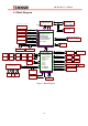
AR-B7230 User’s Manual Table of Contents 1.1 Specifications .................................................................................................................. 7 1.2 Package Contents ............................................................................................................ 9 1.3 Block Diagram .............................................................................................................. 10 2.1 Locations (Top side) .............................................
AR-B7230 User’s Manual 2.3.18 BAT1 (Extrnal Battery Input) .............................................................................. 18 2.3.19 IDE1 ..................................................................................................................... 18 2.3.20 PS2 (Keyboard & Mouse) .................................................................................... 18 2.3.21 J1 ..............................................................................................................
AR-B7230 User’s Manual 1 INTRODUCTION Welcome to the AR-7230 Computer. The AR-7230 incorporates the advanced AMD® M690E & SB600 chipset. It supports the AMD Socket S1 Turion 64 X2 and Sempron Processors, while coming with a 400/533MHz Front Side Bus. The AR-B7230 is a Complete Platform that totally supports EPIC form factor SBC.
AR-B7230 User’s Manual 1.
AR-B7230 User’s Manual z LCD : 1 x Dual Channel 18bits LVDS Interface LCD inverter power connector and ON/OFF control Support 3.3V and 5V LCD AUDIO z Audio Interface : 5.1 CH Audio Realtek ALC655 AC’97 Rev.2.3 with amp.
AR-B7230 User’s Manual 1.2 Package Contents Check if the following items are included in the package. z The quick manual z AR-B7230 z 1 software utility CD z Cooler Optional EPIC Cable Sets (Purchase Separately) z Power Cable (AT) z Power Cable (ATX) z 40/44-Pin IDE Cable z LPT Cable z K/M Cable z Audio Cable (Stereo) z USB Cable (with 4 screws) z COM Cable (10-Pin) x2 z SATA cable z DVI cable Optional Cable (Purchase Separately) z Audio Cable (5.
AR-B7230 User’s Manual 1.
AR-B7230 User’s Manual 2 H/W INFORMATION This chapter describes the installation of AR-B7230. At first, it shows the Function diagram and the layout of AR-B7230. It then describes the unpacking information which you should be careful with, as well as the jumper/switch settings for the AR-B7230 configuration 2.
AR-B7230 User’s Manual CN1 USB Port 3,2 IDE1 CN2 USB Port 5,4 P8 PS2 Keyboard & Mouse CN3 Audio Port J1 Clear CMOS CN5 SATA1 Power (Output) J2 ENABLE SPI/DEBUG COM2 Serial Port 2 J3 RS-232/422/485 SELECT COM3 Serial Port 3 J4 SERIRQ to SL1 Pin B1 CN6 PWR.
AR-B7230 User’s Manual 2.2 Locations (Bottom Side) Figure 3: Locations (Bottom side) 2.3 Connectors and Jumper Setting 2.3.
AR-B7230 User’s Manual 2.3.2 CN2 (USB Port 5,4) 10 2 9 1 PIN SIGNAL PIN SIGNAL 1 +5V 6 D4+ 2 +5V 7 GND 3 D5- 8 GND 4 D4- 9 GND 5 D5+ 10 GND PIN SIGNAL PIN SIGNAL 1 R-OUT 8 A-GND 2 L-OUT 9 A-GND 3 A-GND 10 A-GND 4 A-GND 11 SR-OUT 5 R-IN 12 SL-OUT 6 L-IN 13 LFT-OUT 7 MIC-IN 14 SEN-OUT 2.3.3 CN3 (Audio Port) 14 13 2 1 2.3.4 SATA1 Power (Output) PIN SIGNAL 1 1 +12V 4 2 GND 3 +3.3V 4 +5V 2.3.
AR-B7230 User’s Manual 2.3.6 COM3 (Serial Port 3) 2 10 1 9 PIN SIGNAL PIN SIGNAL 1 DCD3 6 CTS3 2 DSR3 7 DTR3 3 RX3 8 RI3 4 RTS3 9 GND 5 TX3 10 NC PIN SIGNAL PIN SIGNAL 1 POSW 5 CASE 2 GND 6 GND 3 REST 7 GPIO 4 GND 8 GND 2.3.7 CN6 (PWR.SW, Reset, CaseOpen, GPIO) 2 8 1 7 2.3.8 CN7 (ATX Power SB5V Input) 1 3 PIN SIGNAL 1 GND 2 PSON 3 5VSB 2.3.
AR-B7230 User’s Manual 2.3.11 COM4 (Serial Port 4) PIN SIGNAL PIN SIGNAL 1 DCD3 8 RI3 2 DSR3 9 GND 2 14 3 RX3 10 NC 1 13 4 RTS3 11 TX+ 5 TX3 12 TX- 6 CTS3 13 RX+ 7 DTR3 14 RX- PIN SIGNAL PIN SIGNAL 1 STB 14 GND 2 AFD 15 D6 3 D0 16 GND 4 ERR 17 D7 5 D1 18 GND 2.3.
AR-B7230 User’s Manual 2.3.14 FAN2 (System / CPU Fan) PIN SIGNAL 1 GND 2 FAN2 3 DET. 3 1 2.3.
AR-B7230 User’s Manual 6 U2- 16 LCK+ 26 L0- 7 U2+ 17 LCK- 27 L3+ 8 GND 18 GND 28 L3- 9 U1- 19 L2+ 29 +VDD 10 U1+ 20 L2- 30 +VDD 2.3.18 BAT1 (External Battery Input) 1 PIN SIGNAL 1 3VIN 2 GND 2 2.3.
AR-B7230 User’s Manual 2.3.23 J3 2 6 1 5 (Default) 1-2 Short, COM4=RS232 3-4 Short, COM4=RS422 5-6 Short, COM4=RS485 2.3.24 J4 (Default) 1-2 Short,SERIRQ to SL1 Pin B1 2 1 2.3.25 J5 3 1 (Default) 1-2 Short, LCD Power=3.3V 2-3 Short, LCD Power=5.0V 2.3.26 J6 (Default) Short, CF is Master Open, CF is Slave 1 2 2.3.
AR-B7230 User’s Manual 3 BIOS SETTING This chapter describes the BIOS menu displays and explains how to perform common tasks needed to get up and running. It also gives detailed explanation of the elements found in each of the BIOS menus.
AR-B7230 User’s Manual 3.1 Main Setup Once you enter the Award BIOS™ CMOS Setup Utility, the Main Menu will appear on the screen. Use the arrow keys to highlight the item and then use the keys to select the value. You want in each item. Figure 4: Main setup Note : Listed at the bottom of the menu are the control keys. If you need any help with the item fields, you can press the key, and it will display the relevant information.
AR-B7230 User’s Manual 3.2 Advanced Chipset Setup Figure 5: Advance chipset setup Option Choice Description Quick Power On Self Test Enabled Disabled This category speeds up Power On Self Test (POST) after you have powered up the computer. If it is set to Enable, BIOS will shorten or skip some check items during POST. Full Screen Logo Show Enabled Disabled Select Enabled to show the OEM full screen logo if you have add-in BIOS.
AR-B7230 User’s Manual DVMT mode FIXED DVMT Both This item sets the mode for dynamic video memory technology (DVMT).
AR-B7230 User’s Manual 3.3 PnP/PCI setup Figure 6: PnP/PCI setup Option Reset Configuration Data Resources Controlled By Choice Description Enabled Disabled Normally, you leave this field Disabled. Select Enabled to reset Extended System Configuration Data (ESCD) when you exit Setup. If you have installed a new add-on and the system reconfiguration has caused such a serious conflict, then the operating system can not boot.
AR-B7230 User’s Manual IRQ Resources When resources are controlled manually, assign a type to each system interrupt, depending on the type of the device that uses the interrupt N/A 25
AR-B7230 User’s Manual 3.4 Peripherals Setup Figure 7: Peripherals setup Option Choice Description Onboard Serial Port 1 Onboard Serial Port 2 Onboard Serial Port 3 Onboard Serial Port 4 Serial Port 1: 3F8 / IRQ4 Serial Port 2: 2F8 / IRQ3 Serial Port 3: 3E8 / IRQ11 Serial Port 4: 2E8 / IRQ10 Select an address and the corresponding interrupt for each serial port Enabled Disabled Select Enabled if your system contains a Universal Serial Bus (USB) controller and you have USB peripherals USB 2.
AR-B7230 User’s Manual channel separately. 3.5 PC Health Setup This section shows the parameters in determining the PC Health Status. These parameters include temperatures, fan speeds, and voltages.
AR-B7230 User’s Manual 3.6 Boot Setup Figure 9: Boot setup Option Choice Description First / Second / Third Boot Device/Other Boot Device Hard Disk CDROM USB-FDD USB-CDROM LAN Disabled The BIOS attempts to load the operating system from the devices in the sequence selected in these items.
AR-B7230 User’s Manual 3.7 Exit Setup Figure 10: Exit setup Option Save & Exit Setup Load Optimized Defaults Choice Description Pressing on this item for confirmation: Save to CMOS and EXIT (Y/N)? Y When you press on this item you get a confirmation dialog box with a message like this: Load Optimized Defaults (Y/N) ? N 29 Press “Y” to store the selections made in the menus in CMOS – a special section of memory that stays on after you turn your system off.
AR-B7230 User’s Manual Exit Without Saving Pressing on this item for confirmation: Quit without saving (Y/N)? Y This allows you to exit Setup without storing any changes in CMOS. The previous selections remain in effect. This shall exit the Setup utility and restart your computer. When a password has been enabled, you will be prompted to enter your password every time you try to enter Setup. This prevents unauthorized persons from changing any part of your system configuration.