
Instruction Manual


AR-B9622 User’s Guide
3-1
3. SETTING UP THE SYSTEM
This section describes the pin assignments for system’s external connectors and the jumper settings.
z Overview
z System Setting
3.1 OVERVIEW
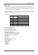
The AR-B9622 is an all-in-one, half-size, 386SX CPU board. This section provides hardware jumper settings, the
connectors’ locations, and the pin assignment.
CAUTION: The CPU board doesn’t support the SIMM-type DRAM.
2
1
0
2
1
0
2
1
02
1
0
+
-
+-
IDE
LCD
J
P
6
1
1
1
1
1
1
1
1
1
1
2
A
B
C
1
2
3
1
2
JP6
1
CN11
H8
H9
H4 H5
CN12
CN2
CN1
U14
1
3
1
5
1
8
1
1
0
0
5
0
U4
1
3
1
5
1
8
1
1
0
0
5
0
U11
U13
CN8
CN9
CN7
CN3
J3
JP4
JP2
P2
P1
J5
J4
J7
J1 J2
J8
105
1
0
4
1
U9
U7
LED2
LM1
LED1
DB1
105
1
0
4
1
U3
CN5
JP1
1
31
51
81
100
50
U2
CN6
CN4
CN10
P3
J
6
J
P
3
U50
J
P
5
J
9
J10
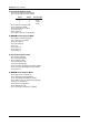
Figure 3-1 External System Location