AR-B9622 User’s Guide AR-B9622 Half Size All-In-One 386SX CPU BOARD User’s Guide Edition: 1.4 Book Number: AR-B9622-98.
AR-B9622 User’s Guide Table of Contents 0. PREFACE ...........................................................................................................................................................0-4 0.1 0.2 0.3 0.4 0.5 0.6 0.7 1. COPYRIGHT NOTICE AND DISCLAIMER......................................................................................................................... 0-4 WELCOME TO THE AR-B9622 CPU BOARD.............................................................................
AR-B9622 User’s Guide 6.7.1 Setting Password ....................................................................................................................................................... 6-7 6.7.2 Password Checking.................................................................................................................................................... 6-7 6.8 LOAD DEFAULT SETTING ..............................................................................................................
AR-B9622 User’s Guide 0.PREFACE 0.1 COPYRIGHT NOTICE AND DISCLAIMER December 1998 Acrosser Technology makes no representations or warranties with respect to the contents hereof and specifically disclaims any implied warranties of merchantability or fitness for any particular purpose.
AR-B9622 User’s Guide 0.6 ORGANIZATION This information for users covers the following topics (see the Table of Contents for a detailed listing): ! ! ! ! ! ! ! ! ! Chapter 1, “Overview”, provides an overview of the system features and packing list. Chapter 2, “System Controller” describes the major structure. Chapter 3, “Setting Up the System”, describes how to adjust the jumper, and the connectors setting.
AR-B9622 User’s Guide 1. OVERVIEW This chapter provides an overview of your system features and capabilities. The following topics are covered: ! ! ! Introduction Packing List Features 1.1 INTRODUCTION The AR-B9622 is a new generation half-size, 386SX board. This card offers much greater performance than the older cards such as support for onboard 4MB DRAM and one RS-232C/485 and three RS-232C ports and one socket for the DiskOnChip from 2MB up to 72MB.
AR-B9622 User’s Guide 1-2
AR-B9622 User’s Guide 2. SYSTEM CONTROLLER This chapter describes the major structure of the AR-B9622 CPU board. The following topics are covered: ! ! ! ! ! ! Microprocessor DMA Controller Keyboard Controller Interrupt Controller Serial Port Parallel Port 2.1 MICROPROCESSOR The AR-B9622 uses the ALI M6117 CPU; it is designed to perform systems like Intel’s 386SX system with deep green features. The 386SX core is the same as M1386SX of Acer Labs. Inc.
AR-B9622 User’s Guide 2.3 KEYBOARD CONTROLLER The 8042 processor is programmed to support the keyboard serial interface. The keyboard controller receives serial data from the keyboard, checks its parity, translates scan codes, and presents it to the system as a byte data in its output buffer. The controller can interrupt the system when data is placed in its output buffer, or wait for the system to poll its status register to determine when data is available.
AR-B9622 User’s Guide 2.4.
AR-B9622 User’s Guide 2.4.2 Real-Time Clock and Non-Volatile RAM The AR-B9622 contains a real-time clock compartment that maintains the date and time in addition to storing configuration information about the computer system. It contains 14 bytes of clock and control registers and 114 bytes of general purpose RAM. Because of the use of CMOS technology, it consumes very little power and can be maintained for long periods of time using an internal Lithium battery.
AR-B9622 User’s Guide 2.5 SERIAL PORT The ACEs (Asynchronous Communication Elements ACE1 to ACE4) are used to convert parallel data to a serial format on the transmit side and convert serial data to parallel on the receiver side. The serial format, in order of transmission and reception, is a start bit, followed by five to eight data bits, a parity bit (if programmed) and one, one and half (five-bit format only) or two stop bits.
AR-B9622 User’s Guide (5) Line Control Register (LCR) Bit 0: Word Length Select Bit 0 (WLS0) Bit 1: Word Length Select Bit 1 (WLS1) WLS1 WLS0 Word Length 0 0 5 Bits 0 1 6 Bits 1 0 7 Bits 1 1 8 Bits Bit 2: Number of Stop Bit (STB) Bit 3: Parity Enable (PEN) Bit 4: Even Parity Select (EPS) Bit 5: Stick Parity Bit 6: Set Break Bit 7: Divisor Latch Access Bit (DLAB) (6) MODEM Control Register (MCR) Bit 0: Data Terminal Ready (DTR) Bit 1: Request to Send (RTS) Bit 2: Out 1 (OUT 1) Bit 3: Out 2 (OUT 2) Bit 4: Lo
AR-B9622 User’s Guide (9) Divisor Latch (LS, MS) LS Bit 0 Bit 1 Bit 2 Bit 3 Bit 4 Bit 5 Bit 6 Bit 7 Bit 0: Bit 1: Bit 2: Bit 3: Bit 4: Bit 5: Bit 6: Bit 7: MS Bit 8 Bit 9 Bit 10 Bit 11 Bit 12 Bit 13 Bit 14 Bit 15 Desired Baud Rate Divisor Used to Generate 16x Clock 300 384 600 192 1200 96 1800 64 2400 48 3600 32 4800 24 9600 12 14400 8 19200 6 28800 4 38400 3 57600 2 115200 1 Table 2-5 Serial Port Divisor Latch 2.
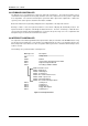
AR-B9622 User’s Guide (4) Printer Status Buffer The system microprocessor can read the printer status by reading the address of the Printer Status Buffer. The bit definitions are described below: 7 6 5 4 3 2 1 0 X X X -ERROR SLCT PE -ACK -BUSY Figure 2-2 Printer Status Buffer NOTE: X represents not used. Bit 7: This signal may become active during data entry, when the printer is off-line during printing, or when the print head is changing position or in an error state.
AR-B9622 User’s Guide (5) Printer Control Latch & Printer Control Swapper The system microprocessor can read the contents of the printer control latch by reading the address of printer control swapper. Bit definitions are as follows: 7 6 X X 5 4 3 2 1 0 STROBE AUTO FD XT INIT SLDC IN IRQ ENABLE DIR(write only) Figure 2-3 Bit’s Definition NOTE: X represents not used. Bit 5: Direction control bit.
AR-B9622 User’s Guide 3. SETTING UP THE SYSTEM This section describes the pin assignments for system’s external connectors and the jumper settings. ! ! Overview System Setting 3.1 OVERVIEW The AR-B9622 is an all-in-one, half-size, 386SX CPU board. This section provides hardware jumper settings, the connectors’ locations, and the pin assignment. CAUTION: The CPU board doesn’t support the SIMM-type DRAM.
AR-B9622 User’s Guide 3.2 SYSTEM SETTINGS Jumper pins allow you to set specific system parameters. Set them by changing the pin location of jumper blocks. (A jumper block is a small plastic-encased conductor [shorting plug] that slips over the pins.) To change a jumper setting, remove the jumper from its current location with your fingers or small needle-nosed pliers. Place the jumper over the two pins designated for the desired setting. Press the jumper evenly onto the pins.
AR-B9622 User’s Guide 3.2.
AR-B9622 User’s Guide (3) PC/104 ISA Signal Description Name Description BUSCLK [Output] The BUSCLK signal of the I/O channel is asynchronous to the CPU clock. RSTDRV [Output] This signal goes high during power-up, low line-voltage or hardware reset SA0 - SA19 The System Address lines run from bit 0 to 19.
AR-B9622 User’s Guide Name -MASTER [Input] Description The MASTER is the signal from the I/O processor which gains control as the master and should be held low for a maximum of 15 microseconds or system memory may be lost due to the lack of refresh -MEMCS16 The Memory Chip Select 16 indicates that the present [Input, Open collector] data transfer is a 1-wait state, 16-bit data memory operation -IOCS16 The I/O Chip Select 16 indicates that the present data [Input, Open collector] transfer is a 1-wait sta
AR-B9622 User’s Guide 3.2.4 PS/2 Mouse Connector (J2) To use the PS/2 mouse, an adapter cable has to be connected to the J2 (6-pin header type) connector. This adapter cable is mounted on a bracket and is included in your AR-B9622 package. The connector for the PS/2 mouse is a Mini-DIN 6-pin connector. The pin assignments for the PS/2 port connector are as follows: DATA 1 N.C. 2 GND 3 VCC 4 CLOCK 5 N.C. 6 J2 1 2 3 4 5 6 Front View Figure 3-7 J2: PS/2 Mouse Connector 3.2.
AR-B9622 User’s Guide 3.2.7 Parallel Port Connector (CN8 & CN9) To use the parallel port, an adapter cable has connected to the CN8 or CN9 (26-pin header type) connector. This adapter cable is mounted on a bracket and is included in your AR-B9622 package. The connector for the parallel port is a 25 pin D-type female connector.
AR-B9622 User’s Guide 3.2.9 Serial Port (1) Full RS-232 Signal / Power Select for COM-A (P3) P3 select the full RS-232 signal or power select for CN10--COM A, if user chooses the power supported then the COM A’s RTS will be instead of the +12VDC signal; and the CN10--COM A’s CTS will be instead of the +5VDC signal.
AR-B9622 User’s Guide (6) RS-232C Connector (CN10) There are four serial ports with EIA RS-232C interface on the AR-B9622. COM A, COM B and COM C use three on-board serial port Phone-Jack 10-pin female connector (CN10) which is located at the right top side of the card. To configure these four serial ports, use the BIOS Setup program to do well, and COM D can be adjust the jumpers on P1 & P2 for choice RS-485 or RS-232C.
AR-B9622 User’s Guide (7) COM-C RI Signal Output Select (JP5) JP5 JP5 1 1 2 2 3 3 RI Signal via J9 output Factory Preset RI Signal via RS-232 Figure 3-19 JP5: COM-C RI Signal Output Select (8) TTL Header (J9) J9 1 RI3 2 TTLO TTL I/O 3 TTLI 4 GROUND Figure 3-20 J9: TTL Header 3.2.
AR-B9622 User’s Guide 3.2.11 RJ-45 Connector (CN4) The CN4 connects RJ-45 header, it’s the standard network header. The following table is CN4 pin assignment. 8 1 Figure 3-22 CN4: RJ-45 Connector PIN (CN4) 1 2 3 4 5 6 7 8 Table 3-7 RJ-45 Pin Assignment FUNCTION TPTX+ TPTX TPRX+ Not Used Not Used TPRX Not Used Not Used 3.2.12 CPU Base Clock Select (JP2) The CPU base clock (Input clock) is twice of its operation clock.
AR-B9622 User’s Guide 4. CRT/LCD FLAT PANEL DISPLAY This section describes the configuration and installation procedure when using the LCD and CRT displays. ! ! ! LCD Flat Panel Displays Supported LCD Panels CRT & LCD Displays 4.1 LCD FLAT PANEL DISPLAYS Using the Flash Memory Writer utility to download the new BIOS file into the ROM chip to configure the BIOS default settings for different types of LCD panels.
AR-B9622 User’s Guide The block diagram shows that AR-B9622 still needs components to be used for LCD panel. The inverter board provides the control for the brightness and the contrast of the LCD panels while the inverter is the one that supplies the high voltage to drive the LCD panel. Each item will be explained further in the section.
AR-B9622 User’s Guide 4.3 CRT & LCD DISPLAY The AR-B9622 supports CRT color monitor, STN, Dual-Scan, TFT, monochrome and color panels. It can be connected to create a compact video solution for the industrial environment. 1MB of V-RAM on-boarded allows a maximum CRT resolution of 800X600 with 256 colors and a LCD resolution of 640X480 with 64K colors. For different VGA display modes, your monitor must possess certain characteristics to display the mode you want. 4.3.
AR-B9622 User’s Guide (2) LCD Panel Display Connector (CN5) Attach a display panel connector to this 44-pin connector with pin assignments shown below: 43 44 1 2 Figure 4-5 CN5: LCD Display Connector Pin Signal 1 GND 3 GND 5 FLM 7 P0 9 P2 11 P4 13 GND 15 P7 17 P9 19 P11 21 P12 23 P14 25 P16 27 GND 29 P19 31 P21 33 P23 35 VCC 37 +12V 39 GND 41 DE 43 GND Table 4-2 LCD Display Assignment 4-4 Pin 2 4 6 8 10 12 14 16 18 20 22 24 26 28 30 32 34 36 38 40 42 44 Signal SHFCLK LP GND P1 P3 P5 P6 P8 P10 GND P13
AR-B9622 User’s Guide 5. INSTALLATION This chapter describes the procedure of the installation. The following topics are covered: ! ! ! Overview Utility Diskette Watchdog Timer 5.1 OVERVIEW This chapter provides information for you to set up a working system based on the AR-B9622 CPU board. Carefully read the details of the CPU board’s hardware descriptions before installation, especially the jumper settings, switch settings and cable connections.
AR-B9622 User’s Guide 5.2.1 VGA Driver WIN 3.1 Driver For the WIN31 operating system, user must in the DOS mode decompress the compress file. And then follow the steps: Step 1: In the DOS mode, execute the SETUP.EXE file. A:\>SETUP Step 2: The screen shows the chip type. Press any key to enter the main menu. Step 3: There are some items for choice to setup. Please choose the item notice the function key defined.
AR-B9622 User’s Guide 5.3 WATCHDOG TIMER This section describes how to use the Watchdog Timer, disabled, enabled, and trigger. The AR-B9622 is equipped with a programmable time-out period watchdog timer. User can use the program to enable the watchdog timer. Once you have enabled the watchdog timer, the program should trigger it every time before it times out.
AR-B9622 User’s Guide 5.3.2 Watchdog Enabled/Disabled - INDEX 37H Bit 7 Reserved. Please do not set this bit. In old version M6117C data sheet, this bit is counter read mode. Bit 6 0 1 Bit 5-0 Other function. Please do not modify these bits. disable watchdog timer enable watchdog timer 5.3.
AR-B9622 User’s Guide (2) Lock Configuration Register mov out nop nop mov out nop nop al, 013h 22h, al al, 000h 23h, al (3) Read the Value at Configuration Register For example, read INDEX 3Ch: Unlock configuration register mov out nop nop in nop nop al, 03ch 22h, al push ax al, 23h Lock configuration register pop ax ; AL - result (4) Write Data to Configuration Register For example, write 0FFh to INDEX 3Bh: Unlock configuration register mov out nop nop mov out nop nop al, 03bh 22h, al al, 0ffh
AR-B9622 User’s Guide 6. BIOS CONSOLE This chapter describes the AR-B9622 BIOS menu displays and explains how to perform common tasks needed to get up and running, and presents detailed explanations of the elements found in each of the BIOS menus. The following topics are covered: ! ! ! ! ! ! ! ! ! BIOS Setup Overview Standard CMOS Setup Advanced CMOS Setup Advanced Chipset Setup Peripheral Setup Auto-Detect Hard Disks Password Setting Load Default Setting BIOS Exit 6.
AR-B9622 User’s Guide 6.2 STANDARD CMOS SETUP The option allows you to record some basic system hardware configuration and set the system clock and error handling. If the CPU board is already installed in a working system, you will not need to select this option anymore. AMIBIOS SETUP - STANDARD CMOS SETUP (C) 1996 American Megatrends, Inc.
AR-B9622 User’s Guide 6.3 ADVANCED CMOS SETUP The option consists of configuration entries that allow you to improve your system performance, or let you set up some system features according to your preference. Some entries here are required by the CPU board’s design to remain in their default settings. AMIBIOS SETUP – ADVANCED CMOS SETUP (C) 1998 American Megatrends, Inc.
AR-B9622 User’s Guide System Keyboard This function specifies that a keyboard is attached to the computer. Primary Display The option is used to set the type of video display card installed in the system. Password Check This option enables password checking every time the computer is powered on or every time the BIOS Setup is executed. If Always is chosen, a user password prompt appears every time the computer is turned on. If Setup is chosen, the password prompt appears if the BIOS executed.
AR-B9622 User’s Guide 6.4 ADVANCED CHIPSET SETUP This option controls the configuration of the board’s chipset. Control keys for this screen are the same as for the previous screen. AMIBIOS SETUP - ADVANCED CHIPSET SETUP (C) 1995 American Megatrends, Inc.
AR-B9622 User’s Guide 6.5 PERIPHERAL SETUP This section is used to configure peripheral features. AMIBIOS SETUP - PERIPHERAL SETUP (C) 1998 American Megatrends, Inc.
AR-B9622 User’s Guide 6.6 AUTO-DETECT HARD DISKS This option detects the parameters of an IDE hard disk drive, and automatically enters them into the Standard CMOS Setup screen. 6.7 PASSWORD SETTING This BIOS Setup has an optional password feature. The system can be configured so that all users must enter a password every time the system boots or when BIOS Setup is executed. User can set either a Supervisor password or a User password. 6.7.
AR-B9622 User’s Guide 6.9 BIOS EXIT This section is used to exit the BIOS main menu in two types situation. After making your changes, you can either save them or exit the BIOS menu and without saving the new values. 6.9.1 Save Settings and Exit This item set in the , , and the new password (if it has been changed) will be stored in the CMOS. The CMOS checksum is calculated and written into the CMOS.
AR-B9622 User’s Guide NOTE: 1. After turn on the computer and the system didn’t detect the boot procedure, please press the [F5] key immediately. The system will pass the CONFIG.SYS and AUTOEXEC.BAT files. 2. The BIOS Flash disk is not the standard accessory. Now the onboard BIOS is the newest BIOS, if user needs adding some functions in the future please contact technical supporting engineers, they will provide the newest BIOS for updating. 3. The file of AMIFLASH.
AR-B9622 User’s Guide 7. SPECIFICATIONS CPU & Chipset: ALI M6117, 33/40 MHz under 5V power supply Bus Interface: PC/104 bus DRAM: 4MB on-board and 4 MB with socket for expansion CRT/LCD Display: 1 MB VRAM HDC: Supports two IDE type hard disk drives FDC: Supports two 5.25” or 3.
AR-B9622 User’s Guide 8. PLACEMENT & DIMENSIONS 8.
AR-B9622 User’s Guide 8.2 DIMENSIONS 2200 350 2090 1290 140 220 840 150 140 400 1350 2900 350 150 3675 5590 6−∅138 150 4710 5000 Unit: mil (1 inch = 25.
AR-B9622 User’s Guide 9. PROGRAMMING RS-485 & INDEX 9.1 PROGRAMMING RS-485 The majority communicative operation of the RS-485 is in the same of the RS-232.
AR-B9622 User’s Guide (5) Basic Language Example a.) Initial 86C450 UART 10 20 30 40 OPEN “COM1:9600,m,8,1”AS #1 LEN=1 REM Reset DTR OUT &H3FC, (INP(%H3FC) AND &HFA) RETURN b.
AR-B9622 User’s Guide 9.2 INDEX Name CN1 CN2 CN3 CN4 CN5 CN6 CN7 CN8 CN9 CN10 CN11 CN12 DB1 J1 J2 J3 J6 J7 J8 J9 U7 LED 1 LED 2 LM1 JP1 JP2 JP3 JP4 JP5 JP6 P3 Function 6-Pin Mini Din Keyboard connector Compact Flash Socket Hard disk (IDE) connectors RJ-45 connector LCD panel display connector Analog monitor (CRT) connector Floppy disk connector Parallel port connector Parallel port connector RS-232 connector 64 pin PC/104 connector bus A & B 40 pin PC/104 connector bus C & D CRT connector AUX.