AR-R5500 Serial Installation Guide 1
Contents 1 2 Introduction of AR-R5500……………………………… 03 1-1 Discrimination……………………………… 03 1-2 Packing List 03 Procedure of Assembly/Disassembly……………………………… 04 2-1 Installing the 2.5”Hard Disk Drive(HDD)………………………...
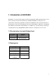
1. Introduction of AR-R5500 AR-R5500 is a system product mainly for industry PC application. With powerful Intel CPU core & diverse memory card extension (mini-PCI, CF, SO-DIM), AR-R5500 can satisfy the users requirement in any Industry application environment. AR-R5500 has diverse physical interface in the front panel, such as 8 or 6*10/100 LAN connectors, build-in LEDs, 2 USB Ports, one COM port, Power Button & Reset Button, Keyboard/Mouse.
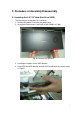
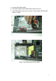
2. Procedure of Assembly/Disassembly 2-1 Installing the 2.5”/3.5”Hard Disk Drive (HDD) The following are instructions for installation. 1. Remove the power via un-plug the power cord. 2. Unscrew the two screws in top cover of AR-R5500, as Fig-01. Fig. 01 Remove the top cover 3. Installing the rubbers on the HDD bracket. 4. Place HDD into HDD bracket and lock HDD and Bracket by screws (4pcs), as Fig-02.
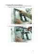
. Connect IDE cable to HDD, 6. Place HDD module (HDD+HDD bracket) back to the case 7. Lock HDD bracket to the chassis by four screws and put HDD with IDE cable, as Fig-03. Fig-03.
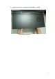
8. Lock the two screws in top cover of AR-R5500, as Fig-04.
2-2 Installing CF card The following are instructions for installation. 1. Remove the Upper door by removing the screws, as Fig-05. Fig-05 Chassis door in bottom case 2.
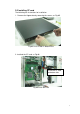
2-3 Installing Extension PCI Card The following are instructions for PCI card installation. 1. AR-R5500 can be extended with a PCI card. 2. Unscrew the two screws in top cover of AR-R5500, as Fig-07. Extension PCI card Fig-07 AR-R5500 Rear View 3. Remove the dummy bracket in PCI slot via unlock the screw as shown in Fig-08. Fig-08.
4. Lock the holder and riser card via locking the screw as shown in Fig-09 Screw driver Fig-09 Lock PCI card 5. Plug the extension PCI card into Riser card and adjust the card into the holder as shown in Fig-10 1.)Plug-in the PCI card 2.
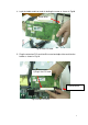
2-4 Installing CPU and Heatsink Module The following are instructions for CPU and Heatsink Module installation. 1. Take off the air flow cover of AR-R5500, as Fig-11 Fig-11 Take off the air flow cover 2.