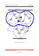
AcroLAN Access Point User’s Guide Version 2000.12.10 ! BSS, ESS and SS ID The basic service set (BSS) is the basic building block of WLAN network. Minimum WLAN BSS may be consist of only two stations. Using access point (AP) and network distribution systems (DS), WLAN service set can be extended arbitrary size – extended service set (ESS). Each service set has its network ID (SSID). All the service sets within an ESS network can have same service ID so that the ESS can support inter-cell ROAMING.
AcroLAN Access Point User’s Guide Version 2000.12.10 Backbone Network AP #`1 SS ID AP #`2 SS ID = Acrowave = Acrowave ROAMING Re-Configuration Required ESS BSS AP #`3 SS ID = Acro Backbone Network Figure 4.
AcroLAN Access Point User’s Guide Chapter 2 Version 2000.12.10 Setup AcroLAN Access Point 2.1 Before You Begin Installation The Acrowave AcroLAN AWL-1100 Series Access Point is a wireless LAN transceiver that can act as the center point of a stand-alone wireless LAN network or as the connection point between wireless and wired networks.
AcroLAN Access Point User’s Guide ! The Acrowave AcroLAN AWL-1100 Series Access Point ! The Access Point power supply ! The Acrowave AcroLAN AWL-1100 Series Installation CD Version 2000.12.10 If any of these items are missing from the package, contact your Access Point supplier.
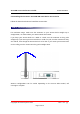
AcroLAN Access Point User’s Guide Version 2000.12.10 2.2 Installing The Acrowave AcroLAN AWL-1100 Series Access Point Follow the instructions below to install the Access Point. STEP 1 Adjust the antennas For maximum range, make sure the antennas on your Access Point straight up or straight down, no matter where your Access Point is mounted. If you keep your Access Point on a table or a desk, turn the antennas so they point straight up.
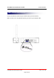
AcroLAN Access Point User’s Guide Version 2000.12.10 STEP 2 Ethernet Cable Connection Connect the Ethernet cable from your wired LAN to your Access Point. Make sure the unit is not powered up when you connect your network cable.
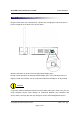
AcroLAN Access Point User’s Guide Version 2000.12.10 STEP 3 Connect The Power Pack Plug the Power Pack into a wall outlet or a power strip, and plug the connector into the power receptacle on the back of the Access Point. All three indicators on top of the access point will be bright green. During normal operation, the indicators will be bright green. If the indicators does not display a solid color or blink, see the “Top Panel Indicator Descriptions” in this manual.
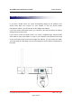
AcroLAN Access Point User’s Guide Version 2000.12.10 STEP 4 Connect Serial Cable If you have a DHCP server, the server automatically assigns an IP address to the Access Point when you connect it to your network. To use the Access Point’s management system, you need to find out the assigned IP address. If you have access to the DHCP server, you can look on the server to find the IP address assigned to the Access Point.
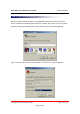
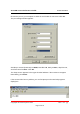
AcroLAN Access Point User’s Guide Version 2000.12.10 STEP 5 Open Terminal Program Open the HyperTerminal program on the workstation attached to the Access Point. These instructions describe HyperTerminal for example, but you can use any terminalemulation program to communicate with the Access Point. This window appears: Type a name for the connection and click OK.
AcroLAN Access Point User’s Guide Version 2000.12.10 Choose the port on your computer to which the serial cable is connected. Click OK. The port settings window appears: Set Bits per second (baud rate) to 19200, Data bits to 8, Parity to None, Stop bits to 1, and Flow control to None. Click OK. The Setup screen appears in the HyperTerminal window. If the text does not appear immediately, press Enter.