MDB Series Dehumidifying Dryers Operation and Installation Manual 50, 100, 150, 255 CMF (85, 170, 255, 380 M3/hr) Part Number: 882.xxxxx.
Write Down Your Serial Numbers Here For Future Reference: _________________________ _________________________ _________________________ _________________________ _________________________ _________________________ We are committed to a continuing program of product improvement. Specifications, appearance, and dimensions described in this manual are subject to change without notice. DCN No. ____________ © Copyright 2013 All rights reserved.
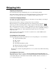
Shipping Info Unpacking and Inspection You should inspect the large dehumidifying dryer for possible shipping damage. Thoroughly check the equipment for any damage that might have occurred in transit, such as broken or loose wiring and components, loose hardware and mounting screws, etc. In the Event of Shipping Damage According to the contract terms and conditions of the Carrier, the responsibility of the Shipper ends at the time and place of shipment.
Returns Do not return any damaged or incorrect items until you receive shipping instructions from the shipping department. Credit Returns Prior to the return of any material authorization must be given by the manufacturer. A RMA number will be assigned for the equipment to be returned. Reason for requesting the return must be given. ALL returned material purchased from the manufacturer returned is subject to 15% ($75.00 minimum) restocking charge. ALL returns are to be shipped prepaid.
Table of Contents CHAPTER 1: SAFETY .............................................................. VII 1-1 1-2 1-3 How to Use This Manual .......................................................................................... vii Safety Symbols Used in this Manual .................................................................. vii Warnings and Precautions ........................................................................................ ix Responsibility ........................................
CHAPTER 4: CONTROLS ........................................................ 26 4-1 4-2 4-3 4-4 4-5 4-6 Controller Descriptions ............................................................................................26 Operating the Dryer .................................................................................................26 DryPro Data Entry....................................................................................................28 Single Hopper Dryer Setup ......................
Chapter 1: Safety 1-1 How to Use This Manual Use this manual as a guide and reference for installing, operating, and maintaining the mid-sized dehumidifying dryer. The purpose is to assist you in applying efficient, proven techniques that enhance equipment productivity. This manual covers only light corrective maintenance. No other maintenance should be undertaken without first contacting a service engineer. The General Information section outlines models covered, standard features, and safety features.
Dryer Safety Tags Hazard Alert Symbol Mandatory Symbol Description/Explanation Preventative Maintenance High Voltage Hazard. The electrical enclosure is supplied with 3-phase electrical power. Use caution when using or maintaining this product. Every six months inspect all electrical connections for secure attachment. For further information see the Maintenance Chapter in this manual. Auto start Hazard. Equipment may start at any time. Lock out/tag out before servicing the machine.
1-2 Warnings and Precautions Our equipment is designed to provide safe and reliable operation when installed and operated within design specifications, following national and local safety codes. This may include, but is not limited to OSHA, NEC, CSA, SPI, and any other local, national and international regulations.
1-3 Responsibility These machines are constructed for maximum operator safety when used under standard operating conditions and when recommended instructions are followed in the maintenance and operation of the machine. All personnel engaged in the use of the machines should become familiar with their operation as described in this manual. Proper operation of the machine promotes safety for the operator and all workers in its vicinity.
NEVER try to pull material out of the dryer with your hands while it is running! Before you start the dehumidifying dryer, check the following: • Remove all tools from the dryer; • Be sure no objects (tools, nuts, bolts, clamps, bars) are laying in the area; If your dryer has been inoperative or unattended, check all settings before starting. At the beginning of your shift and after breaks, verify that the controls and other auxiliary equipment are functioning properly.
When you need to perform maintenance or repair work on a dehumidifying dryer above floor level, use a solid platform or a hydraulic elevator. If there is a permanently installed catwalk on your dryer, use it. The work platform should have secure footing and a place for tools and parts. DO NOT climb on the dehumidifying dryer, machines, or work from ladders. If you need to repair a large component, use appropriate handling equipment.
Chapter 2: General Information 2-1 Models Covered in This Manual This manual provides operation, installation, and maintenance instructions for 50, 100, 150 and 225 cfm Dehumidifying Dryers with DryPro control. Model numbers are listed on the serial tag. Make sure you know the model and serial number of your equipment before contacting the manufacturer for parts or service.
This system is a closed loop, because ambient (outside) air is never introduced into the process air. See Figure 1. Our dehumidifying dryers use the closed loop system, because the process air is typically much drier than ambient air, even after carrying moisture out of the plastic resin. Recycling process air maintains drying efficiency at a consistently high level. (see Figure 1). Figure 1: Air Flow Diagram.
Absorbed water is driven from saturated desiccant by heating it to a high temperature (reducing the desiccant's capacity to hold water) and forcing air through it. This moisture removal process is called "regeneration". The Process/Regeneration Cycle Our dehumidifying dryers have two desiccant beds. While one bed is on-line in the process air loop, the other is off-line being regenerated. When a desiccant bed is on-line, it absorbs moisture from the process air.
Closed Loop and Heat Recovery Option After bed breakthrough (see Process/Regeneration Cycle) the desiccant is hot and needs to be cooled down to avoid a temperature spike when the beds are switched. Instead of using ambient air to cool down the desiccant, the closed loop option recirculates a portion of the dry air from the desiccant bed currently on-line for the process.
Safety Devices and Interlocks This section includes information on safety devices and procedures that are inherent to the large dehumidifying dryer. This manual is not intended to supersede or alter safety standards established by the user of this equipment. Instead, the material contained in this section is recommended to supplement these procedures in order to provide a safer working environment.
In addition to the safety devices listed above, these dehumidifying dryers are equipped with a line cord plug. This allows the operator or maintenance personnel to unplug the system from its power source and tag it out. The plug can then be tagged with any number of approved electrical lockout tags available at most electrical supply stores. Always disconnect and lockout all electrical power and pneumatic (i.e. compressed air) sources prior to servicing or cleaning the dehumidifying dryer.
Material saver with temperature setback Process recipes (200 max, over 50 pre-loaded) Drying temperature Residence time Regrind percent Density Setback temperature Throughput calculation Alphanumeric hopper / process ID Hour & KWH meters (total & resettable service) Audible & visible alarm 7 day timer Sequence shutdown Available supply voltages of 208, 230, 460, 575/3/60 and 220, 400/3/50 2-5 Options Options can tailor your dehumidifying dryer system to meet the exact requirements of the drying task be
2-6 Dimensions and Specifications General Information 20
2-7 Silo Dehumidification System Airflow range – Mid- Size 50-225 cfm (In most cases, a 50 cfm dryer may not be adequate). Metal silos are affected by the weather conditions surrounding them. They can become damp internally from sweat on their sidewalls caused by changes in humidity and temperature and this moisture can be transferred to the material stored in the silo. Silo dehumidifiers are not intended to dry the material stored inside the silo.
Chapter 3: Installation 3-1 Positioning Your Dryer The dehumidifying dryer system was designed to be wheeled into place. The entire assembly is mounted on a rugged, compact frame and is equipped with sturdy, 4” (10 cm) heavy-duty casters. It is important to leave room to access the dryer from the front, rear, and at least one side, for repair and regular maintenance.
Process Blower The air connection marked “Delivery” should be blowing air while the “Return” connection has suction. Delivery port Return port Note: The return port is hosed to the process filter inlet. Regeneration Blower Regeneration filter The regeneration filter inlet shown should be sucking air in for the regeneration cycle.
3-4 Process Air Connections Between the Dryer and Drying Hopper Remove the cap plugs from the inlet, discharge and bleed tubes before operation. Use high-temperature flexible dryer hose to connect the dryer to the drying hopper. Keep the delivery hose as short as possible to minimize heat loss. Insulated dryer hose is available for maximum energy savings. Do not shorten the return hose. Make sure the hoses are not kinked.
3-6 Drying Hopper Removing the Rust Inhibitor Rust preventative has been applied to internal unfinished surfaces. Remove rust inhibitor before using the drying hopper. Using a non-water based degreasing agent, clean all inside surfaces of the drying hopper. Allow components to dry thoroughly. Inspect the inside of the drying hopper for loose connections, foreign objects, or a blocked diffuser.
Chapter 4: Controls 4-1 Controller Descriptions The DryPro dryer control system is designed to control all ACS cabinet, medium and large dryers. These dryers have separate Process and regeneration blowers and up to four desiccant beds. The DryPro control system includes the following features: • • • • • Customer configurable drying hopper identification. Enhanced diagnostics for quick troubleshooting. Support for up to 3 drying hoppers. Support for Compact Flash memory cards.
The drying hoppers can be started in a staggered manner where the control waits an adjustable time between starting each drying hopper. ACS recommends that the customer execute an auto-tune cycle on the regeneration beds and drying hoppers when the dryer is placed into service for the first time. The regeneration blower starts. 2 • When air flow is verified, the bed in regeneration is brought to the pre-set regeneration temperature.
4-3 DryPro Data Entry Values and text are changed using on-screen keypads. The screen will display either a numeric or alphanumeric keypad, depending on the type of data entry. The appropriate keypad appears when a changeable value is pressed. Minimum & maximum values are indicated for each numeric value. Values outside of these limits are rejected. Passwords. All functions except starting and stopping the dryer require a password.
System Setup. Use the “System Setup” display to • Select whether temperatures are displayed in Fahrenheit or Celsius. • Select metric or standard measure for volume & density. • Set the alarm silence duration The following are set at the factory and should only be accessed to commission a new display when the configuration can not be restored from compact flash. • Select the appropriate thermocouple type. • Set the dryer size.
1. Set the normal process temperature setpoint. The material saver setpoints are set on the Overdry Protect Setup screen. 2. Set the deviation limits for process temperature alarms. Also set the standby time to allow the drying temperature to rise to the set value at system startup. 3. Set the process ID for the hopper. This can be a press ID, product name, or any other value that makes sense. Also, the hopper volume and heater KW are set. These values are used in throughput and KWH calculations. 4.
Process Autotune Screen Use the Process Autotune screen to start or stop autotune for the process heater. Also, values can be manually entered, although this is generally discouraged. Autotune should be performed on initial startup after installation, and any time a process change occurs that affects air flow through the hopper. The values will change after a successful autotune.
Use this screen for entering data for new recipes. Pressing the “Save” button will write the new recipe to Compact Flash and return to the Material Setup screen. Pressing “Cancel” will return to the Material Setup screen without making a new recipe. Regen Setup screen Use this screen to control the regen process. Bed switch on dewpoint can be set up here as well as on the Dewpoint Setup screen. Regen heat time can be based on time only or on bed break with an override time.
Dewpoint Setup screen Use this screen to set up switch on dewpoint parameters, as well as the high dewpoint alarm value. Overdry Protect Setup screen Use this screen to configure overdry protection for your material. Setback setpoint is the secondary drying temperature to use. Setback @ is the hopper exit temperature that will cause the secondary setpoint to be activated. Setback Delay is how long the exit temperature must be above the Setback @ setting before setback is activated.
Hour Meters Setup screens Use these screens to view and / or reset the various hour meters associated with the dryer. To reset a meter, press the “R” button for 3 seconds. Note that only the “Since Service” values are resettable. Additionally, hour meters can be viewed via the Main Menu screen, but not reset.
4-5 Single Hopper Dryer Operation Main Menu screen 9 8 1 2 3 7 6 4 5 The Main Menu is the main navigational screen for the DryPro control system. No password is required to access : 1) Dryer Status 3) Regen Status 6) Alarms 7) Hour Meters 9) Splash screen Operator or above password is required for 2) Hopper status.
Supervisor or above password is required for: 4) Setup Menu 5) Auto Start Timers Service password access is required for Service screens (ACS qualified personnel only). No password is required to access 8) Users screen, however functionality depends on current password access. E F D 1) Dryer Status screen I G B C A H A) Dryer Start / Stop / Restart button B) Dryer Status message C) Auto Start Timer Active indicator. D) Process temperature, setpoint, dewpoint, and exit temperature.
H) Regen Heater Temperature. This appears adjacent to the bed currently in the regeration cycle. Each Regen heater also may indicate “AT” when autotune is in progress for a regen heater. I) Regen Exit Temperature. Touching any current temperature value will display the associated graphical trend screen. 2) Hopper Status screen This screen displays the current values for the drying hopper as well as allowing for changing the drying temperature. Operator or above password access is required.
3) Regen Status screen This screen displays all current status values for the regen subsystem. As with the Dryer Status screen, touching any current temperature value will display the associated graphical trend screen. 4) Setup Menu screen See section 4-4.
This screen is used to control the auto start functionality of the dryer. AutoStart must be enabled for entered times to take effect. A value of 12:00 AM is considered a non-value and has no effect. This screen requires supervisor password access. 6) Alarm History screen. This screen displays a list of alarms that have occurred with descriptions and time stamps. 7) Hour Meter Display screens These screens are used to view current hour meter and KWH meter values.
8) Users screen This screen is used to change passwords for User1 or Super1. That user must be logged on to be able to change the password. User2 & Super2 passwords cannot be changed. 1) Splash screen This screen is used to view the current PLC and HMI software versions. Graphical Trend screens.
These screens are used to graphically track all dryer temperatures: Process inlet (shown above) Process exit Regen heater Regen exit Dew point 4-6 Program Upgrade Procedures The DryPro PLC and touch screen use either a EEPROM module or compact flash memory card for program upgrades. Occasionally, a program upgrade will become available from ACS for the DryPro PLC, touch screen or both. Follow the instructions in this document to upgrade the specific component.
- Turn dip switch 2 on (slide to right side). - Turn on Power. Wait for “Backup” indicator to turn off. Turn off power. Remove memory cassette. Replace cover. Turn off dip switch 2. Resume normal operation. Restore settings that have changed. Return upgrade kit to ACS for credit. Power up the dryer, inspect and verify the new version number(s) Start the dryer as required. Dry-Pro HMI field upgrade instructions - Turn off power. Remove existing compact flash – note orientation.
Dryer & Drying Hopper Faults Faults fall into two broad categories. • Critical Faults – Shuts down equipment. • Non-Critical Faults – Does not shut down equipment. Critical faults are assigned to conditions that could cause damage to either the dryer components or the material in the drying hopper while non-critical faults are assigned to conditions that would allow an undesirable or inefficient Process condition to exist.
When a fault condition occurs, the screen displays an “Alarm Banner” showing the time, date and a brief description of the alarm. Optionally, the control will sound a klaxon and turn on an alarm lamp. The alarm banner, klaxon and lamp do not distinguish between critical and noncritical alarms. The klaxon can be silenced and the alarm lamp turned off by pressing the “Push to Silence” button on either the alarm banner or alarm history display.
Regen Air Blower Safety Fault Regen Air Dirty Filter Alert Regen Exhaust Sensor Error Alert Temperature Alarms The control checks for high low and fail to change (loop break) alarm conditions on the regeneration inlet temperature and the drying hopper process supply air temperature. It also checks for high temperature on the dryer exit and the pre-cooler (or after-cooler) if the option is installed.
The other key difference is the addition of the new pushbutton on the Drying Hopper screens. For example, the green “Enable” icon on this screen is new. There may be other text that is shown in the box.
Chapter 5: Operation 5-1 Pre-Startup Checks 1. Verify that the drying hopper is clean of rust-prohibitive oil or any foreign objects. 2. Verify that process and return hose connections are tight. 3. If your dryer has a water-cooled aftercooler/Precooler or closed loop cooler, make sure that sufficient cooling water flows properly through the coil and that you have bled any trapped air from the system.
5-3 Shutdown 1. Turn off the conveying system supplying the drying hopper. 2. When processing is complete, close the hopper slide gate and shut down any in-line companion equipment, such as the aftercooler. 3. Turn the dryer ON/OFF selector switch to the SEQUENCE SHUTDOWN position. The sequence shutdown operation turns off process heaters and keeps the process blower on for twenty minutes to cool down the process.
Chapter 6: Operation 6-1 Work Rules The installation, operation, and maintenance of this equipment is to be conducted in accordance with all applicable work and safety codes for the installation location. This may include, but is not limited to, OSHA, NEC, CSA, and any other local, national, and international regulations. In addition, you must observe the following specific work rules: Keep these operating instructions on hand and follow them when installing, operating, or maintaining your dryer.
Recommendations for Cleaning and Replacing Filters • Turn off and/or lock out electrical power to the dryer. • Remove the threaded fastener securing the filter access cover, and then remove the cover. • Remove the nut on the center retaining rod to remove the filter cartridge. Vacuuming Try vacuum-cleaning a soiled filter first. Vacuuming removes most large particles and surface contaminants, and may suffice for the first time you clean a filter.
Preventative Maintenance Checklist Dehumidifying Dryer Systems System model # Serial # Date/ By Every week Date/ By Date/ By Date/ By Date/ By Date/ By Date/ By Date/ By Date/ By Date/ By Date/ By Date/ By Date/ By Nov Dec Inspect all filters for wear, replace/clean if dirty or worn. Every month Jan Feb Mar Apr May Jun Jul Aug Sep Oct Lock out electrical power and inspect electrical wiring for integrity.
6-3 Servicing the Dew Point Monitor The accuracy of the dew point monitor on dehumidifying dryer systems depends on proper operation of the dew point sensor and the control board. The dew point sensor is in the process air stream and is therefore susceptible to contamination. Dew point sensor life depends on: Air temperature and flow passing over the sensor. The amount of fines (dust) in the process air. The amount of plasticizer vapor in the process air.
6-5 Replacing Worn Desiccant Make sure desiccant beds are sufficiently cool before replacing worn desiccant. 1. Disconnect the electrical supply. 2. Remove the rear panels to expose the desiccant beds. 3. Access the desiccant cans in one of the following ways: • Remove the entire bed from the frame. • Remove the hoses located at the top of the beds. • Remove the thermocouple and fittings. Make a note of the correct location for each. • loosen the 4 knurled nuts below the desiccant can.
Thermocouple and fittings Desiccant cans Knurled Nut Couplers with “T” handles Can Assembly Part # 892.04505.00 The pre-packed can assembly is available from parts and service. See “Contact Information” Before re-packing the beds, determine the proper amount of desiccant for the dryer being serviced. See Figure 7 on the following page for more information. Desiccant can assemblies prepacked from the manufacturer are available and simply drop into the frame.
9. Re-install the rear and side shrouds. Re-connect the compressed air supply and electrical power. Figure 7: Required Desiccant Amounts per Bed; Type 4X Desiccant (2 beds per unit) Dryer CFM 50 100 150 225 Large bead (Type 4X) Part no. lbs. Kg 1.5 0.68 3.0 1.362 W00000892 9.0 4.086 9.0 4.086 Small bead (Type 4X) Part no. lbs. Kg 10.5 4.75 21.0 9.534 W00000893 30.0 13.620 30.0 13.620 Total per bed lbs. Kg 12 5.44 24.0 10.896 39.0 17.706 39.0 17.
6. Re-install the heater and heater plate assemblies in reverse order. Install new heater gaskets and securely tighten all fasteners. Heater loops should not touch each other. “Hot Spots” lead to premature heater failure! 7. Reinstall the wires based on the sketch you made earlier. 8. Secure the heater access cover. 6-7 Replacing the Regeneration Heater The dehumidifying dryers use heater elements located below each desiccant bed. Disconnect and lock out power before you replace heater elements! 1.
Chapter 7: Troubleshooting Problem Little or no air coming from the process delivery tube. Possible cause Dirty filter. Desiccant beds are contaminated by material or plasticizer leaking into the system. Blower overload has tripped. Blower fins filled with dust or contaminants. Suction in delivery tube, pressure from the return tube. Phase is reversed on power drop coming into the dryer. Process heaters are faulty. Loss or reduction of process air temperature.
Problem Loss or reduction in drying capacity. (Cont’d.) PLC Regeneration Bed LED indicators both off. Possible cause Airflow valve sticking or failing to shift. Blower fins filled with dust or contaminants. Insufficient power to PLC (Power LED is off). Faulty PLC (PLC Power light is on, Run light is off, and/or Error light is on). Regenerating bed cool down. Blower Input indicator is off. PLC Regeneration Heater Left/Right output indicators both off. Process air in hightemperature condition.
Problem Nothing displays when the controller is turned on. Possible cause The internal mechanism is not inserted properly into the housing. The power supply is not connected to its terminals properly. No power is supplied, or the supplied power is not within the specified range. Disconnect switch or Control Power switch not set to ON. Control Power fuse blown. Input polarity on thermocouple is wrong or connection is wrong. No compensating lead wires used for extension of the thermocouple.
Chapter 8: Appendix 8-1 Technical Assistance Parts and Service Department The ACS Customer Service Group will provide your company with genuine OEM quality parts manufactured to engineering design specifications, which will maximize your equipment’s performance and efficiency. To assist in expediting your phone or fax order, please have the model and serial number of your unit when you contact us. A customer replacement parts list is included in this manual for your convenience.
The following design information is provided for your reference: 1. No modifications are allowed to this equipment that could alter the CE compliance 2. Ambient temperature: 0 degrees Celsius – Maximum (104 degrees Fahrenheit) 3. Humidity range: 50% relative humidity 4. Altitude: Sea level 5. Environment: Clean and non-explosive 6. Radiation: None 7. Vibration: Minimal, i.e. machine mounting 8. Allowable voltage fluctuation: +/- 10% 9.
8-3 Parts Diagrams Valve Assemblies – MDB 85 & 170 Appendix 62
Notes Appendix 63