ACR100F SIMFlash (CCID) Reference Manual Subject to prior notice Subject to change changewithout without prior notice info@acs.com.hk info@acs.com.hk www.acs.com.hk www.acs.com.
Table of Contents 1.0. Introduction ............................................................................................................... 3 2.0. Features ..................................................................................................................... 4 3.0. System Block Diagram ............................................................................................. 5 4.0. Power Supply .................................................................................
1.0. Introduction More than just a smart card reader, the ACR100F (CCID) SIMFlash has a built-in flash memory and is designed for both accessing plug-in (SIM-sized) smart cards and for data or application storage. It is ideal for GSM solutions such as GSM management software and VoIP applications, electronic payment systems, e-commerce, home banking, transportation, and computer and network access.
2.0. Features USB combo device – works as smart card reader and mass storage USB 2.0 Hi-Speed interface for flash and USB 1.1 Full-Speed interface for smart card reader Bus-powered – no need for separate power supply or battery Plug and play – CCID support brings utmost mobility With protective USB cap and keychain loop Smart card reader: o Supports plug-in (SIM-sized) cards o Supports ISO 7816 Class A, B and C (5 V, 3 V, 1.
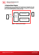
3.0. .0. System Block Diagram The USB Hub Controller is the communication interface between the PC and the MCU of the smart card and flash memory via USB port connection. The 1 GB flash memory is available for the end-user to use as storage. In Windows Explorer, the device is detected as a removable disk. The ACR100F is powered from the USB port without other external power supply. Smart Card Interface Circuit USB Interface USB 2.
4.0. Power Supply The ACR100F requires a voltage of 5 V DC, 100 mA regulated power supply. It gets the power supply from the PC. 4.1. Status LED Bicolor LED in front of the reader indicates the activation status of the smart card and flash memory interface. GREEN LED: Flashing slowly (turns on 200 ms for every 2 seconds) Indicates smart card interface part is powered up and in the standby state. Either the smart card has not been inserted or the smart card has not been powered up (if it is inserted).
5.0. Smart Card Interface The interface between the ACR100F and the inserted smart card follows the specifications of ISO 7816-3. 5.1. Smart Card Power Supply VCC (C1) The current consumption of the inserted card must not be higher than 50 mA. 5.2. Programming Voltage VPP (C6) According to ISO 7816-3, the smart card contact C6 (VPP) supplies the programming voltage to the smart card.
6.0. USB Interface The connection of the ACR100F to a computer through a USB port follows a USB Standard. 6.1. Communication Parameters The ACR100F is connected to a computer through USB as specified in the USB Specification. The ACR100F is working in high-speed mode, i.e. 480 Mbps, for the flash memory and USB 1.1 full-speed mode for smart card interface. Pin Signal Function 1 VBUS +5 V power supply for the reader 2 D- Differential signal transmits data between ACR100F and PC.
7.0. Communication Protocol ACR100F interfaces with the host via USB connection. It is a compounded device consisting of two interfaces: Chip Card Interface Device and Mass Storage. The ACR100F Smart Card Interface shares the same core as the smart card interface of the ACR38 CCID. The Smart Card Interface will be identified as “ACR38-112c” once the reader FW is obtained. (The command for this will be discussed later on). CCID covers all the protocols required for operating smart cards and PIN.
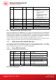
Offset Field Size dwFeatures 40 44 48 49 50 52 53 Value Description 00010030h The Smart card reader supports the following features: Automatic ICC clock frequency change according to parameters Automatic baud rate change according to frequency and FI,DI parameters TPDU level exchange with the smart card reader Maximum message length accepted by the smart card reader is 271 bytes 4 dwMaxCCIDMessa geLength bClassGetRespo nse bClassEnvelope wLCDLayout bPINSupport bMaxCCIDBusySl ots 0000010Fh
7.1.1.2. PC_to_RDR_IccPowerOff Deactivate the card slot. Offset 0 1 5 6 7 Field Si ze bMessageType dwLength bSlot 1 4 bSeq abRFU 1 3 Value Description 63h 00000000h 1 Size of extra bytes of this message Identifies the slot number for this command Sequence number for command Reserved for future use The response to this message is the RDR_to_PC_SlotStatus message. 7.1.1.3. PC_to_RDR_GetSlotStatus Get current status of the slot.
Offset Field Size AbRFU 7 Value 3 Description Reserved for future use The response to this message is the RDR_to_PC_Parameters message. 7.1.1.6. PC_to_RDR_ResetParameters Reset slot parameters to default value.
Offset Field Size bClockStop 14 Value Description ICC Clock Stop Support 00h = Stopping the Clock is not allowed 01h = Stop with Clock signal Low 02h = Stop with Clock signal High 03h = Stop with Clock either High or Low 1 Protocol Data Structure for Protocol T=1 (dwLength=00000007h) Offset Field Size Value Description 00h B7-4 – FI – Index into the table 7 in ISO/IEC 7816-3:1997 selecting a clock rate conversion factor B3-0 – DI - Index into the table 8 in ISO/IEC 7816-3:1997 selecting a baud
7.1.2.2. RDR_to_PC_SlotStatus This message is sent by the smart card reader in response to PC_to_RDR_IccPowerOff, PC_to_RDR_GetSlotStatus, PC_to_RDR_Abort messages and Class specific ABORT request.
7.1.2.3. RDR_to_PC_Parameters This message is sent by the smart card reader in response to PC_to_RDR_GetParameters, PC_to_RDR_ResetParameters and PC_to_RDR_SetParameters messages. Offset 0 1 5 6 7 8 Field Siz e bMessageType dwLength bSlot bSeq bStatus bError 1 4 1 1 Value Description 82h Size of extra bytes of this message Same value as in Bulk-OUT message Same value as in Bulk-OUT message Slot status register as defined in CCID section 4.2.1 Slot error register as defined in CCID section 4.2.
FIRMWARE 10 bytes data for firmware version MAX_C The maximum number of command data bytes. MAX_R The maximum number of data bytes that can be requested to be transmitted in a response. C_TYPE The card types supported by the smart card reader. This data field is a bitmap with each bit representing a particular card type. A bit set to '1' means the corresponding card type is supported by the reader and can be selected with the SELECT_CARD_TYPE command.
Appendix A.
Appendix B.