
Instruction Manual


Document Title Here
Document Title Here
Document Title Here
info@acs.com.hk
www.acs.com.hk
Page 15 of 18
ACR100F (CCID) Reference Manual
Version 3.00
info@acs.com.hk
www.acs.com.hk
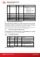
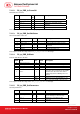
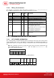
7.1.2.3. RDR_to_PC_Parameters
This message is sent by the smart card reader in response to PC_to_RDR_GetParameters,
PC_to_RDR_ResetParameters and PC_to_RDR_SetParameters messages.
Offset Field Siz
e
Value Description
0
bMessageType
1
82h
1
dwLength
4
Size of extra bytes of this message
5
bSlot
1
Same value as in Bulk-OUT message
6
bSeq
1
Same value as in Bulk-OUT message
7
bStatus
1
Slot status register as defined in CCID section
4.2.1
8
bError
1
Slot error register as defined in CCID section
4.2.1 and this specification section 5.2.8
9
bProtocolNum
1
Specifies what protocol data structure follows.
00h = Structure for protocol T=0
01h = Structure for protocol T=1
The following values are reserved for future
use.
80h = Structure for 2-wire protocol
81h = Structure for 3-wire protocol
82h = Structure for I2C protocol
10
abProtocolData
Structure
Byt
e
arra
y
Protocol Data Structure as summarized in
section 5.2.3.
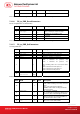
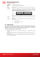
7.1.3. Commands Accessed via PC_to_RDR_XfrBlock
7.1.3.1. GET_READER_INFORMATION
This command returns relevant information about the particular smart card reader model and the
current operating status such as the firmware revision number, the maximum data length of a
command and response, the supported card types, and whether a card is inserted and powered up or
not.
Note: This command can only be used after the logical smart card reader communication has
been established using the SCardConnect( ) API. For details of ScardConnect( ) API,
please refer to PC/SC specification.
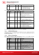
Pseudo-APDU
CLA INS P1 P2 Lc
FF
H
09
H
00
H
00
H
10
H
Command format (abData field in the PC_to_RDR_XfrBlock)
Response data format (abData field in the RDR_to_PC_DataBlock)
FIRMWARE MAX
_C
MAX
_R
C_TY
PE
C_SE
L
C_ST
AT