ACR100I SIMFlash II (CCID) SIMFlash with Embedded Mifare Reference Manual info@acs.com.hk Subject to change without prior notice www.acs.com.
Table of Contents 1.0. Introduction ............................................................................................................. 3 2.0. Features ................................................................................................................... 4 3.0. System Block Diagram ............................................................................................ 5 4.0. Power Supply.......................................................................................
1.0. Introduction ACR100I SIMFlash II (CCID) is not an ordinary smart card reader. Its memory storage comes with NAND Flash memory for high capacity data storage needs. This can be partitioned into a maximum of three sections as desired by the user. ACR100I SIMFlash II (CCID) also has an embedded Mifare 1K chip for various contactless card functions, such as logical and physical access.
2.0. Features USB Combo Device – works as a smart card reader and mass storage device SIM-sized slot for smart card at USB 2.0 full speed NAND Flash support at USB 2.0 high speed Plug-and-Play – CCID support brings supreme compatibility and mobility Extractable USB Two color LEDs for smart card and NAND Flash status indication Smart card reader: o Supports plug in (SIM-sized) cards o Supports ISO 7816 Class A, B, and C (5 V, 3 V, 1.
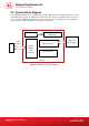
3.0. System Block Diagram The USB Hub Controller is the communication interface between the PC and the MCU of the smart card and the flash memory via USB port connection. The flash memory is available for the end-user to use as storage. In Windows Explorer, the device is detected as a removable disk. The ACR100I is powered from the USB port without other external power supply. Antenna for Mifare Chip Mifare Chip Smart Card USB Interface Interface Circuit SIM-sized Smart Card 2 PORT USB 2.
4.0. Power Supply The ACR100I requires a voltage of 5 V DC, 300 mA regulated power supply, and gets the power supply from PC. 4.1. Status LED Bicolor LED in front of the reader indicates the activation status of the smart card and flash memory interface. GREEN LED: Flashing slowly (turns on 200 ms for every 2 seconds) Indicates that the ACR100I is powered up and in the standby state. Either the smart card has not been inserted or the smart card has not been powered up (if it is inserted).
5.0. Smart Card Interface The interface between the ACR100I and the inserted smart card follows the specifications of ISO 7816-3. 5.1. Smart Card Power Supply VCC (C1) The current consumption of the inserted card must not be higher than 50 mA. 5.2. Programming Voltage VPP (C6) According to ISO 7816-3, the smart card contact C6 (VPP) supplies the programming voltage to the smart card.
6.0. USB Interface The connection of the ACR100I to a computer through a USB port follows a USB Standard. 6.1. Communication Parameters The ACR100I is connected to a computer through USB as specified in the USB Specification 2.0. The ACR100I is working in high-speed mode, i.e. 480 Mbps. Pin Signal Function 1 VBUS +5 V power supply for the reader (Max 500 mA, Normal 300 mA) 2 D- Differential signal transmits data between ACR100I and PC.
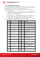
7.0. Communication Protocol ACR100I shall interface with the host with through USB connection. A specification, namely CCID, has been released within the industry defining such protocol for the USB chip-card interface devices. CCID covers all the protocols required for operating smart cards and PIN. The configurations and usage of USB endpoints on ACR100I shall follow CCID Section 3. overview is summarized below: An 1. Control Commands are sent on a control pipe (default pipe).
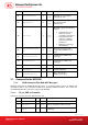
Offset Field Size Value Description 32 dwSynchProtocols 4 00000 000h ACR100I does not support synchronous card 36 dwMechanical 4 00000 000h ACR100I does not support special mechanical characteristics ACR100I supports the following features: 40 dwFeatures 4 00010 030h Automatic ICC clock frequency change according to parameters Automatic baud rate change according to frequency and FI,DI parameters TPDU level exchange with ACR100I Maximum message length accepted by ACR100I is 271 b
Offset Field bSeq 5 Size Value Description 1 Sequence number for command 6 bPowerSelect 1 Voltage that is applied to the ICC 00h – Automatic Voltage Selection 01h – 5 volts 02h – 3 volts 7 abRFU 2 Reserved for future use The response to this message is the RDR_to_PC_DataBlock message and the data returned is the Answer To Reset (ATR) data. 7.1.1.2. PC_to_RDR_IccPowerOff Deactivate the card slot.
7.1.1.4. PC_to_RDR_XfrBlock Transfer data block to the ICC. Offset Field Size Value Description 0 bMessageType 1 1 dwLength 4 Size of abData field of this message 5 bSlot 1 Identifies the slot number for this command 6 bSeq 1 Sequence number for command Used to extend the CCIDs Block Waiting Timeout for this current transfer. The CCID will timeout the block after “this number multiplied by the Block Waiting Time” has expired.
7.1.1.7. PC_to_RDR_SetParameters Set slot parameters. Offset Field Size Value Description 0 bMessageType 1 1 dwLength 4 Size of extra bytes of this message 5 bSlot 1 Identifies the slot number for this command 6 bSeq 1 Sequence number for command 1 Specifies what protocol data structure follows. 00h = Structure for protocol T=0 01h = Structure for protocol T=1 The following values are reserved for future use.
Protocol Data Structure for Protocol T=1 (dwLength=00000007h) Offset Field Size Value Description B7-4 – FI – Index into the Table 7 in ISO/IEC 7816-3:1997 selecting a clock rate conversion factor 10 bmFindexDindex 1 B3-0 – DI - Index into the Table 8 in ISO/IEC 7816-3:1997 selecting a baud rate conversion factor B7-2 – 000100b 11 BmTCCKST1 B0 – Checksum type (b0=0 for LRC, b0=1 for CRC 1 B1 – Convention used (b1=0 for direct, b1=1 for inverse) Note: The CCID ignores this bit.
7.1.2. CCID Bulk-IN Messages The Bulk-IN Messages are used in response to the Bulk-OUT Messages. ACR100I shall follow the CCID Bulk-IN Messages as specified in CCID Section 4. This section lists the CCID Bulk-IN Messages to be supported by ACR100I. 7.1.2.1. RDR_to_PC_DataBlock This message is sent by ACR100I in response to PC_to_RDR_IccPowerOn, PC_to_RDR_XfrBlock and PC_to_RDR_Secure messages.
Offset Field Size Value Description value = 00h Clock running 01h Clock stopped in state L bClockStatus 9 1 02h Clock stopped in state H 03h Clock stopped in an unknown state All other values are RFU. 7.1.2.3.
7.1.3. 7.1.3.1. Commands Accessed via PC_to_RDR_XfrBlock GET_READER_INFORMATION This command returns relevant information about the particular ACR100I model and the current operating status, such as the firmware version number; the maximum data length of a command and response; the supported card types; and whether a card is inserted and powered up or not. Note: This command can only be used after the logical smart card reader communication has been established using the SCardConnect() API.
powered up: 00H: no card inserted 01H: card inserted, not powered up 03H: card powered up 7.2. Mass Storage Mass Storage Device Class specifies all protocols required for data transaction between the Host (computer) and storage devices. The configurations and usage of USB endpoints on ACR100I shall follow Mass Storage Class Bulk-Only Transport in Section 3 (Protocol Code) of the USB Mass Storage Device Specification. This document is available at: www.usb.org.
Appendix A.
Appendix B.