ACR38x Smart Card Reader Reference Manual V6.02 Subject to change without prior notice info@acs.com.hk www.acs.com.
Table of Contents 1.0. Introduction ............................................................................................................... 4 1.1. 1.2. Reference Documents ........................................................................................................... 4 Symbols and Abbreviations ...................................................................................................4 2.0. Features ............................................................................
List of Tables Table 1 : Symbols and Abbreviations ..................................................................................................... 4 Table 2 : USB Interface Wiring ............................................................................................................... 9 Table 3 : Supported Card Types .......................................................................................................... 39 Table 4 : Response Status Codes .......................................
1.0. Introduction The ACR38x PC-linked Smart Card Reader acts as an interface for the communication between a computer and a smart card. Different types of smart cards have different commands and different communication protocols, which in most cases, prevent direct communication between a smart card and a computer. The ACR38x Smart Card Reader establishes a uniform interface from the computer to the smart card for a wide variety of cards.
2.0. Features • USB 2.0 Full Speed Interface • Smart Card Reader: • • o Supports ISO 7816 Class A, B and C (5 V, 3 V, 1.
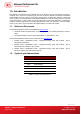
3.0. Smart Card Support 3.1. MCU Cards The ACR38x is a PC/SC-compliant smart card reader that supports ISO 7816 Class A, B and C (5 V, 3 V, and 1.8 V) smart cards. It also works with MCU cards following the T=0 and T=1 protocol. The card ATR indicates the specific operation mode (TA2 present; bit b5 of TA2 must be 0) and when that particular mode is not supported by the ACR38x, the reader will reset the card to a negotiable mode.
4.0. Smart Card Interface The interface between the ACR38x and the inserted smart card follows the specification of ISO 78163 with certain restrictions or enhancements to increase the practical functionality of ACR38x. 4.1. Smart Card Power Supply VCC (C1) The current consumption of the inserted card must not be higher than 50 mA. 4.2. Programming Voltage VPP (C6) According to ISO 7816-3, the smart card contact C6 (VPP) supplies the programming voltage to the smart card.
5.0. Power Supply The ACR38x requires a voltage of 5 V DC, 100 mA, regulated, power supply. The ACR38x gets power supply from the computer (through the cable supplied along with each type of reader). 5.1. Status LED The LED indicates the activation status of the smart card interface: • Flashing slowly (turns on 200 ms every 2 seconds) Indicates ACR38x is powered up and in the standby state. Either the smart card has not been inserted or the smart card has not been powered up (if it is inserted).
6.0. USB Interface 6.1. Communication Parameters The ACR38x is connected to a computer through USB as specified in the USB Specification 2.0. The ACR38x is working in full speed mode, i.e. 12 Mbps.
7.0. Communication Protocol During normal operation, the ACR38x acts as a slave device with regard to the communication between a computer and the reader. The communication is carried out in the form of success command-response exchanges. The computer transmits a command to the reader and receives a response from the reader after the command has been executed. A new command can be transmitted to the ACR38x only after the response to the previous command has been received.
00h = command successfully executed Otherwise = error in command data, or command cannot be executed A table listing the possible values of the status byte and the corresponding meaning is given in Appendix B. Data Length Number of subsequent data bytes, and is encoded in 2 bytes. The first byte (MSB) and second byte (LSB) represent data length N. Data Data contents of the command. For a READ_DATA command, for example, the data bytes would contain the contents of the memory addresses read from the card.
8.0. Memory Card Type Selection 8.1. By Property Sheet User could invoke the reader setting property sheet by selecting the Properties of ACR38 Smart Card Reader device under the Device Manager. Figure 1: ACR38x Reader Setting Property Sheet The ACR38x needs to be removed, and then reconnected to the computer in order for the change to take effect. 8.2. By Programmatic Method The card type can also be changed the program run-time using Vendor Specific extension API of PC/SC.
Example: int main() { long rv; long nCardType = 15; // SLE4418 – refer to inf for more info BYTE cbOutBuffer[10]; SCARDCONTEXT hctx; SCARDHANDLE hsc; DWORD dwActievProtocol; DWORD dwBytesRet; rv = SCardEstablishContext(SCARD_SCOPE_SYSTEM,NULL,NULL,&hctx); if (rv != SCARD_S_SUCCESS) return rv; rv = SCardConnect( hctx, ”ACS ACR38U 0”, SCARD_SHARE_DIRECT, // This allows apps to connect to // PC/SC even without card inserted 0, &hsc, &dwActiveProtocol); if (rv != SCARD_S_SUCCESS) { // error handling … return rv
9.0. Commands 9.1. Control Commands The Control Commands are in charge of the internal operation of the ACR38x. They do not directly affect the card inserted in the ACR38x and are therefore independent of the selected card type. 9.1.1.
9.1.2. SELECT_CARD_TYPE This command sets the required card type. The firmware in ACR38x adjusts the communication protocol between reader and the inserted card according to the selected card type. Command Format Header Instruction 01h 02h Data length Data LEN TYPE 00h 01h Where: TYPE See Appendix A for the value to be specified in this command for a particular card to be used. Response Data Format Header Data length Status LEN 01h 9.1.3.
9.1.4. SET_CARD_PPS This command sends PPS Request to the smart card. This command should work in pair with SET_READER_PPS. Command Format Header Instruction 01h 0Ah Data length Data LEN PPS Request MSB LSB Where: LEN Length of PPS request. Typical value is “4”. PPS Request PPS Request to send to the card (Please refer to ISO/IEC 7816-3:1997 Section 7 for details of PPS request).
9.2. Card Commands The Card Commands are directed toward the card inserted in the ACR38x. The structure of these commands and the data transmitted in the commands and responses depend on the selected card type. 9.2.1. MCU Card Command Set 9.2.1.1. RESET_WITH_5_VOLTS_DEFAULT This command powers up the card inserted in the ACR38x and performs a card reset. If the card is powered up when the command is being issued, only a reset of the card is carried out. The power supply to the card is not switched off.
Response data format Header Data length Status ATR LEN 01h … Where: ATR Answer-To-Reset as transmitted by the card according to ISO 7816-3. Note: The ATR is only returned in the reader response if the communication protocol of the card is compatible with the ACR38x, i.e., if the card can be processed by the reader. Otherwise, ACR38x returns an error status and deactivates the smart card interface. 9.2.1.3. POWER_OFF This command powers off the card inserted in the ACR38x.
Response Data Format Header Data length Status LEN BYTE 1 … … BYTE N SW1 SW2 01h Where: BYTE x Response data from card (if any). SW1 SW2 Status code returned by the card. 9.2.1.5. EXCHANGE_TPDU_T1 This command exchanges an APDU command/response pair between the cards inserted in the ACR38x and the host computer using T1 protocol. Command Format Header Instruction 01h A1h Data length LEN MSB LSB Data T1 TPDU Frame … Where: LEN Length of APDU command data, N.
9.2.2. Memory Card Command Set 9.2.2.1. Memory Card – 1, 2, 4, 8, and 16 Kbit I2C Card 9.2.2.1.1. SELECT_PAGE_SIZE This command will choose the page size to read the smart card. The default value is 8-byte page write. It will reset to default value whenever the card is removed or the ACR38x is powered off. Send Buffer Format SCardTransmit Send Buffer CLA INS P1 P2 Lc (P3) FFh 01h 00h 00h 01h Page size Where: Page size = 03h for 8-byte page write. = 04h for 16-byte page write.
Where: BYTE x Data read from memory card. SW1 SW2 = 90 00h if no error. 9.2.2.1.3. WRITE_MEMORY_CARD Send Buffer Format SCardTransmit Send Buffer CLA INS FFh D0h Byte Address MSB (P1) LSB (P2) MEM_L (P3) Byte 1 .... .... Byte n Where: Byte Address Memory address location of the memory card. MEM_L Length of data to be written in the memory card. Byte x Data to be written to the memory card. Response Buffer Format SCardTransmit Receive Buffer SW1 SW2 Where: SW1 SW2 = 90 00h if no error.
Response Buffer Format SCardTransmit Receive Buffer SW1 SW2 Where: SW1 SW2 = 90 00h if no error. 9.2.2.2.2. READ_MEMORY_CARD Send Buffer Format SCardTransmit Send Buffer CLA INS Byte Address MSB (P1) LSB (P2) MEM_L (P3) FFh Where: INS = B0h for 32, 64, 128, 256, 512 kbit iic card. = 1011 000*b for 1024kbit iic card, where * is the MSB of the 17 bit addressing. Byte Address Memory address location of the memory card. MEM_L Length of data to be read from the memory card.
= 1101 000*b for 1024 kbit iic card, where * is the MSB of the 17 bit addressing. Byte Address Memory address location of the memory card. MEM_L Length of data to be written in the memory card. Byte x Data to be written to the memory card. Response Buffer Format SCardTransmit Receive Buffer SW1 SW2 Where: SW1 SW2 = 90 00h if no error. 9.2.2.3. Memory Card – ATMEL AT88SC153 9.2.2.3.1.
9.2.2.3.2. WRITE_MEMORY_CARD Send Buffer Format SCardTransmit Send Buffer CLA INS FFh P1 Bye Address (P2) MEM_L (P3) Byte 1 .... .... Byte n 00h Where: INS = D0h for writing zone 00b. = D1h for writing zone 01b. = D2h for writing zone 10b. = D3h for writing zone 11b. = D4h for writing fuse. Byte Address Memory address location of the memory card. MEM_L Length of data to be written in the memory card. MEM_D Data to be written to the memory card.
Response Buffer Format SCardTransmit Receive Buffer SW1 SW2 Where: SW1 SW2 = 90 00h if no error. 9.2.2.3.4. INITIALIZE_AUTHENTICATION Send Buffer Format SCardTransmit Send Buffer CLA INS P1 P2 Lc (P3) FFh 84h 00h 00h 08h Q(0) Q(1) … Q(7) Where: Q(0),Q(1)…Q(7) Host random number, 8 bytes. Response Buffer Format SCardTransmit Receive Buffer SW1 SW2 Where: SW1 SW2 = 90 00h if no error. 9.2.2.3.5.
9.2.2.4. Memory Card – ATMEL AT88SC1608 9.2.2.4.1. READ_MEMORY_CARD Send Buffer Format SCardTransmit Send Buffer CLA INS Zone Address (P1) Byte Address (P2) MEM_L (P3) FFh Where: INS = B0h for reading user zone. = B1h for reading configuration zone or reading fuse. Zone Address = 0000 0A10A9A8b, where A10 is the MSB of zone address. = don’t care for reading fuse. Byte Address = A7A6A5A4 A3A2A1A0b is the memory address location of the memory card. = 1000 0000b for reading fuse.
Response Buffer Format SCardTransmit Receive Buffer SW1 SW2 Where: SW1 SW2 = 90 00h if no error. 9.2.2.4.3. VERIFY_PASSWORD Send Buffer Format SCardTransmit Send Buffer CLA INS P1 P2 Lc (P3) FFh 20h 00h 00h 04h Data RP Pw(0) Pw(1) Pw(2) Where: Pw(0),Pw(1),Pw(2) Passwords to be sent to memory card.
Response Buffer Format SCardTransmit Receive Buffer SW1 SW2 Where: SW1 SW2 = 90 00h if no error. 9.2.2.4.5. VERIFY_AUTHENTICATION Send Buffer Format SCardTransmit Send Buffer CLA INS P1 P2 Lc (P3) FFh 82h 00h 00h 08h Q1(0) Q1(1) … Q1(7) Where: Byte Address Memory address location of the memory card. Q1(0),Q1(1)…Q1(7) Host challenge, 8 bytes. Response Buffer Format SCardTransmit Receive Buffer SW1 SW2 Where: SW1 SW2 = 90 00h if no error. 9.2.2.5.
Response Buffer Format SCardTransmit Receive Buffer BYTE 1 … … BYTE N PROT 1 … … PROT L SW1 SW2 Where: BYTE x Data read from memory card. PROT y Bytes containing the protection bits of the data bytes read. SW1 SW2 = 90 00h if no error.
Where: BYTE x Data read from the memory card. SW1 SW2 = 90 00h if no error. 9.2.2.5.3. WRITE_MEMORY_CARD Send Buffer Format SCardTransmit Send Buffer CLA INS FFh Byte Address MSB (P1) LSB (P2) MEM_L (P3) Byte 1 .... .... Byte N D0h Where: MSB Byte Address = 0000 00A9A8b is the memory address location of the memory card. LSB Byte Address = A7A6A5A4 A3A2A1A0b is the memory address location of the memory card. MEM_L Length of data to be written in the memory card.
card. MEM_L Length of data to be written to the memory card. Byte x Byte values to be compared with the data in the card starting at Byte Address. BYTE 1 is compared with the data at Byte Address; BYTE N is compared with the data at (Byte Address+N-1). Response Buffer Format SCardTransmit Receive Buffer SW1 SW2 Where: SW1 SW2 = 90 00h if no error. 9.2.2.5.5.
9.2.2.5.6. READ_PRESENTATION_ERROR_COUNTER_MEMORY_CARD (SLE and SLE 5528) 4428 This command is used to read the presentation error counter for the secret code. Send Buffer Format SCardTransmit Send Buffer CLA INS P1 P2 MEM_L (P3) FFh B1h 00h 00h 00h Response Buffer Format SCardTransmit Receive Buffer ERRCNT DUMMY 1 DUMMY 2 SW1 SW2 Where: ERRCNT The value of the presentation error counter. DUMMY Three bytes dummy data read from the card. SW1 SW2 = 90 00h if no error. 9.2.2.6.
The arrangement of the protection bits in the PROT bytes is as follows: PROT 1 P8 P7 P6 P5 P4 PROT 2 P3 P2 P1 P16 P15 P14 P13 P12 … P11 P10 P9 .. .. .. .. .. .. P18 P17 Where: Px is the protection bit of BYTE x in the response data. ‘0’ byte is write protected. ‘1’ byte can be written. 9.2.2.6.2. WRITE_MEMORY_CARD Send Buffer Format SCardTransmit Send Buffer CLA INS P1 FFh D0h 00h Byte Address (P2) MEM_L (P3) Byte 1 .... ....
Byte x Byte values to be compared with the data in the card starting at Byte Address. BYTE 1 is compared with the data at Byte Address; BYTE N is compared with the data at (Byte Address+N-1). Response Buffer Format SCardTransmit Receive Buffer SW1 SW2 Where: SW1 SW2 = 90 00h if no error. 9.2.2.6.4. PRESENT_CODE_MEMORY_CARD (SLE 4442 and SLE 5542) This command is used to submit the secret code to the memory card to enable the write operation with the SLE 4442 and SLE 5542 card.
9.2.2.6.5. READ_PRESENTATION_ERROR_COUNTER_MEMORY_CARD (SLE 4442 and SLE 5542) This command is used to read the presentation error counter for the secret code. Send Buffer Format SCardTransmit Send Buffer CLA INS P1 P2 MEM_L (P3) FFh B1h 00h 00h 00h Response Buffer Format SCardTransmit Receive Buffer ERRCNT DUMMY 1 DUMMY 2 DUMMY 3 SW1 SW2 Where: ERRCNT The value of the presentation error counter. DUMMY Three bytes dummy data read from the card. SW1 SW2 = 90 00h if no error. 9.2.2.6.6.
9.2.2.7. Memory Card – SLE 4406/SLE 4436/SLE 5536/SLE 6636 9.2.2.7.1. READ_MEMORY_CARD Send Buffer Format SCardTransmit Send Buffer CLA INS P1 FFh B0h 00h Byte Address (P2) MEM_L (P3) Where: Byte Address = Memory address location of the memory card. MEM_L Length of data to be read from the memory card. Response Buffer Format SCardTransmit Receive Buffer BYTE 1 … … BYTE N SW1 SW2 Where: BYTE x Data read from memory card. SW1 SW2 = 90 00h if no error. 9.2.2.7.2.
write operation. Command Format SCardTransmit SendBuffer CLA INS P1 FFh D0h 00h Byte Address MEM_L MODE BYTE 02h Where: Byte Address = Memory address location of the memory card. LEN = 5 + MEM_L MODE Specifies the write mode and backup option: 00h: Write 01h: Write with carry 02h: Write with backup enabled (SLE 4436, SLE 5536 and SLE 6636 only) 03h: Write with carry and with backup enabled (SLE 4436, SLE 5536 and SLE 6636 only) BYTE Byte value to be written in the card.
Response Data Format SCardTransmit Receive Buffer SW1 SW2 Where: SW1 SW2 = 90 00h if no error. 9.2.2.7.4. AUTHENTICATE_MEMORY_CARD (SLE 4436, SLE 5536 and SLE 6636) This command is used to read a card authentication certificate from an SLE 5536 or SLE 6636 card.
Appendix A. Supported Card Types The following table shows the value that must be specified in the SET_CARD_TYPE command for a particular card type to be used, and how the bits in the response to the GET_ACR_STAT command correspond with the respective card types.
Appendix B.