
User guide


ACR38x – Reference Manual info@acs.com.hk
Version 6.02
www.acs.com.hk
Page 33 of 40
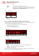
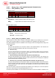
The arrangement of the protection bits in the PROT bytes is as follows:
PROT 1 PROT 2 …
P8 P7 P6 P5 P4 P3 P2 P1 P16 P15 P14 P13 P12 P11 P10 P9 .. .. .. .. .. .. P18 P17
Where:
Px is the protection bit of BYTE x in the response data.
‘0’ byte is write protected.
‘1’ byte can be written.
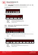
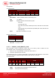
9.2.2.6.2. WRITE_MEMORY_CARD
Send Buffer Format
SCardTransmit Send Buffer
CLA INS P1 Byte Address (P2) MEM_L (P3) Byte 1 .... .... Byte N
FFh D0h 00h
Where:
Byte Address = A7A6A5A4 A3A2A1A0b is the memory address location of the memory
card.
MEM_L Length of data to be written in the memory card.
Byte x Data to be written in the memory card.
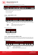
Response Buffer Format
SCardTransmit Receive Buffer
SW1 SW2
Where:
SW1 SW2 = 90 00h if no error.
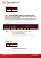
9.2.2.6.3. WRITE_PROTECTION_MEMORY_CARD
Each byte specified in the command is internally in the card compared with the byte stored at the
specified address and if the data match, the corresponding protection bit is irreversibly programmed to
‘0’.
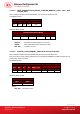
Send Buffer Format
SCardTransmit Send Buffer
CLA INS P1 Byte Address (P2) MEM_L (P3) Byte 1 .... .... Byte N
FFh D1h 00h
Where:
Byte Address = 000A4 A3A2A1A0b
(00h to 1Fh) is the protection memory address
location of the memory card.
MEM_L Length of data to be written to the memory card.