
Owner's manual

ACR3801 – Reference Manual info@acs.com.hk
Version 2.01
www.acs.com.hk
Page 38 of 62
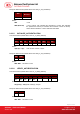
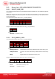
Response Data Format (abData field in the RDR_to_PC_DataBlock)
PROT 1 … … PROT L SW1 SW2
Where:
PROT y Bytes containing the protection bits
SW1 SW2 = 90 00h if no error
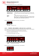
The arrangement of the protection bits in the PROT bytes is as follows:
PROT 1 PROT 2 …
P8 P7 P6 P5 P4 P3 P2 P1 P16 P15 P14 P13 P12 P11 P10 P9 .. .. .. .. .. .. P18 P17
Px is the protection bit of BYTE x in the response data
‘0’ byte is write protected
‘1’ byte can be written
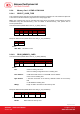
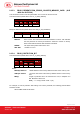
8.3.5.5. WRITE_MEMORY_CARD
Command Format (abData field in the PC_to_RDR_XfrBlock)
Pseudo-APDU
CLA INS
Byte Address
MEM_L Byte 1 .... .... Byte N
MSB LSB
FFh D0h
Where:
MSB Byte Address = 0000 00A
9
A
8
b is the memory address location of the memory card
LSB Byte Address = A
7
A
6
A
5
A
4
A
3
A
2
A
1
A
0
b is the memory address location of the memory
card
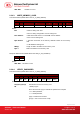
MEM_L Length of data to be written to the memory card
Byte x Data to be written to the memory card
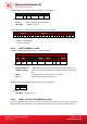
Response Data Format (abData field in the RDR_to_PC_DataBlock)
SW1 SW2
Where:
SW1 SW2 = 90
00h if no error
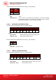
8.3.5.6. WRITE_PROTECTION_MEMORY_CARD
Each byte specified in the command is used in the card to compare the byte stored in a specified
address location. If the data match, the corresponding protection bit is irreversibly programmed to ‘0’.