ACR38x CCID Smart Card Reader Reference Manual V6.04 Subject to change without prior notice info@acs.com.hk www.acs.com.
Table of Contents 1.0. Introduction ............................................................................................................... 4 1.1. 1.2. Reference Documents ........................................................................................................... 4 Symbols and Abbreviations ...................................................................................................4 2.0. Features ............................................................................
List of Tables Table 1 : Symbols and Abbreviations ..................................................................................................... 4 Table 2 : USB Interface Wiring ............................................................................................................... 9 Table 3 : Supported Card Types .......................................................................................................... 57 Table 4 : Response Error Codes ........................................
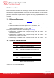
1.0. Introduction The ACR38x (CCID) PC-linked Smart Card Reader acts as an interface for the communication between a computer and a smart card. Different types of smart cards have different commands and different communication protocols, which, in most cases, prevent direct communication between a smart card and a computer. The ACR38x (CCID) Smart Card Reader establishes a uniform interface from the computer to the smart card for a wide variety of cards.
2.0. Features • USB 2.0 Full Speed Interface • Plug and Play – CCID support brings utmost mobility • Smart Card Reader: • o Supports ISO 7816 Class A, B and C (5 V, 3 V, 1.8 V) cards o Supports microprocessor cards with T=0 or T=1 protocol o Supports memory cards o Supports PPS (Protocol and Parameters Selection) o Features Short Circuit Protection Application Programming Interface: o Supports PC/SC o Supports CT-API (through wrapper on top of PC/SC) • Supports Android™ OS 3.
3.0. Smart Card Support 3.1. MCU Cards The ACR38x (CCID) is a PC/SC compliant smart card reader that supports ISO 7816 Class A, B and C (5 V, 3 V, and 1.8 V) smart cards. It also works with MCU cards following either the T=0 and T=1 protocol. The card ATR indicates the specific operation mode (TA2 present; bit b5 of TA2 must be 0) and when that particular mode is not supported by the ACR38x (CCID), the reader will reset the card to a negotiable mode.
4.0. Smart Card Interface The interface between the ACR38x (CCID) and the inserted smart card follows the specification of ISO 7816-3 with certain restrictions or enhancements to increase the practical functionality of ACR38x (CCID). 4.1. Smart Card Power Supply VCC (C1) The current consumption of the inserted card must not be higher than 50 mA. 4.2. Programming Voltage VPP (C6) According to ISO 7816-3, the smart card contact C6 (VPP) supplies the programming voltage to the smart card.
5.0. Power Supply The ACR38x (CCID) requires a voltage of 5 V DC, 100 mA, regulated, power supply. The ACR38x (CCID) gets power supply from the computer (through the cable supplied along with each type of reader). 5.1. Status LED The LED indicates the activation status of the smart card interface: • • • Flashing slowly (turns on 200 ms every 2 seconds) Indicates ACR38x (CCID) is powered up and in the standby state.
6.0. USB Interface 6.1. Communication Parameters The ACR38x (CCID) is connected to a computer through USB as specified in the USB Specification 2.0. The ACR38x (CCID) is working in full speed mode, i.e. 12 Mbps.
7.0. Communication Protocol ACR38x (CCID) shall interface with the host through the USB connection. A specification, namely CCID, has been released within the industry defining such a protocol for the USB chip-card interface devices. CCID covers all the protocols required for operating smart cards. The configurations and usage of USB endpoints on ACR38x (CCID) shall follow CCID Rev 1.0 Section 3. An overview is summarized below: 1. Control Commands are sent on control pipe (default pipe).
Offset Field Size Value Description ACR38x (CCID) supports the following features: 40 dwFeatures 4 • Automatic ICC clock frequency change according to parameters • Automatic baud rate change according to frequency and FI,DI parameters • TPDU level change with ACR38x (CCID) 44 dwMaxCCIDMessageLength 4 Maximum message length accepted by ACR38x (CCID) is 271 bytes. 48 bClassGetResponse 1 Insignificant for TPDU level exchanges. 49 bClassEnvelope 1 Insignificant for TPDU level exchanges.
8.0. Memory Card Type Selection SELECT_CARD_TYPE command must be executed first before other memory card commands. This command powers up and down the selected card inserted in the card reader and performs a card reset. This command can only be used after the logical smart card reader communication has been established using the SCardConnect() API. For details of SCardConnect() API, please refer to PC/SC specifications. For the Memory Card Command Set, please refer to Section 9.3.
9.0. Commands 9.1. CCID Command Pipe Bulk-OUT Messages ACR38x (CCID) shall follow the CCID Bulk-OUT Messages as specified in CCID Rev 1.0 Section 4.1. In addition, this specification defines some extended commands for operating additional features. This section lists the CCID Bulk-OUT Messages to be supported by ACR38x (CCID). 9.1.1. PC_to_RDR_IccPowerOn This command activates the card slot and returns ATR data from the card.
Offset Field Size Value Description 5 bSlot 1 Identifies the slot number for this command. 6 bSeq 1 Sequence number for command. 7 abRFU 3 Reserved for future use. The response to this message is the RDR_to_PC_SlotStatus message. 9.1.4. PC_to_RDR_XfrBlock This command transfers data block to the ICC. Offset Field Size Value 0 bMessageType 1 6Fh 1 dwLength 4 Size of abData field of this message. 5 bSlot 1 Identifies the slot number for this command.
9.1.6. PC_to_RDR_ResetParameters This command resets slot parameters to the default value. Offset Field Size Value Description 0 bMessageType 1 6Dh 1 DwLength 4 00000000h 5 BSlot 1 Identifies the slot number for this command. 6 BSeq 1 Sequence number for command. 7 AbRFU 3 Reserved for future use. Size of extra bytes of this message. The response to this message is the RDR_to_PC_Parameters message. 9.1.7. PC_to_RDR_SetParameters This command sets the slot parameters.
Offset Field Size Value Description B0 – 0b, B7-2 – 000000b 11 bmTCCKST0 B1 – Convention used (b1=0 for direct, b1=1 for inverse) Note: The CCID ignores this bit. 1 12 bGuardTimeT0 1 Extra Guardtime between two characters. Add 0 to 254 etu to the normal guardtime of 12 etu. FFh is the same as 00h.
Offset Field Size Value Description ICC Clock Stop Support 00h = Stopping the Clock is not allowed 14 bClockStop 1 01h = Stop with Clock signal Low 02h = Stop with Clock signal High 03h = Stop with Clock either High or Low 15 bIFSC 1 16 bNadValue 1 Size of negotiated IFSC 00h Only support NAD = 00h The response to this message is the RDR_to_PC_Parameters message. Page 17 of 58 ACR38x (CCID) – Reference Manual Version 6.04 info@acs.com.hk www.acs.com.
9.2. CCID Bulk-IN Messages The Bulk-IN messages are used in response to the Bulk-OUT messages. ACR38x (CCID) shall follow the CCID Bulk-IN Messages as specified in CCID Rev 1.0 Section 4.2. This section lists the CCID Bulk-IN Messages to be supported by ACR38x (CCID). 9.2.1. RDR_to_PC_DataBlock This command is sent by ACR38x (CCID) in response PC_to_RDR_XfrBlock and PC_to_RDR_Secure messages.
Offset 9 9.2.3. Field Size Value Value: 00h = Clock running 01h = Clock stopped in state L 02h = Clock stopped in state H 03h = Clock stopped in an unknown state All other values are RFU. 1 bClockStatus Description RDR_to_PC_Parameters This message is sent by ACR38x (CCID) in response to PC_to_RDR_GetParameters, PC_to_RDR_ResetParameters and PC_to_RDR_SetParameters messages. Offset Field Size Value 0 bMessageType 1 82h 1 dwLength 4 Size of extra bytes of this message.
9.3. Memory Card Command Set This section contains the Memory Card Command Set for ACR38x (CCID). 9.3.1. Memory Card – 1, 2, 4, 8 and 16 Kbit I2C Card 9.3.1.1. SELECT_CARD_TYPE This command powers up and down the selected card that is inserted in the card reader and performs a card reset. Note: This command can only be used after the logical smart card reader communication has been established using the SCardConnect() API. For details of SCardConnect() API, please refer to PC/SC specifications.
Response Data Format (abData field in the RDR_to_PC_DataBlock) SW1 SW2 Where: SW1 SW2 = 90 00h if no error 9.3.1.3.
9.3.2. Memory Card – 32, 64, 128, 256, 512, and 1024 Kbit I2C Card 9.3.2.1. SELECT_CARD_TYPE This command powers up and down the selected card that is inserted in the card reader and performs a card reset. Note: This command can only be used after the logical smart card reader communication has been established using the SCardConnect() API. For details of SCardConnect() API, please refer to PC/SC specifications.
9.3.2.3.
Response Data Format (abData field in the RDR_to_PC_DataBlock) SW1 SW2 Where: SW1 SW2 = 90 00h if no error Page 24 of 58 ACR38x (CCID) – Reference Manual Version 6.04 info@acs.com.hk www.acs.com.
9.3.3. Memory Card – ATMEL AT88SC153 9.3.3.1. SELECT_CARD_TYPE This command powers up and down the selected card that is inserted in the card reader and performs a card reset. It will also select the page size to be 8-byte page write. Note: This command can only be used after the logical smart card reader communication has been established using the SCardConnect() API. For details of SCardConnect() API, please refer to PC/SC specifications.
9.3.3.3. WRITE_MEMORY_CARD Command Format (abData field in the PC_to_RDR_XfrBlock) Pseudo-APDU CLA INS P1 FFh Byte Address MEM_L Byte 1 .... ....
Response Data Format (abData field in the RDR_to_PC_DataBlock) SW2 ErrorCnt SW1 90h Where: SW1 = 90h SW2 (ErrorCnt) = Error Counter. FFh indicates the verification is correct. 00h indicates the password is locked (or exceeded the maximum number of retries). Other values indicate the current verification has failed. 9.3.3.5.
9.3.4. Memory Card – ATMEL AT88C1608 9.3.4.1. SELECT_CARD_TYPE This command powers up and down the selected card that is inserted in the card reader and performs a card reset. It will also select the page size to be 16-byte page write. Note: This command can only be used after the logical smart card reader communication has been established using the SCardConnect() API. For details of SCardConnect() API, please refer to PC/SC specifications.
9.3.4.3.
Response Data Format (abData field in the RDR_to_PC_DataBlock) SW1 SW2 ErrorCnt 90h Where: SW1 = 90h SW2 (ErrorCnt) = Error Counter. FFh indicates the verification is correct. 00h indicates the password is locked (or exceeded the maximum number of retries). Other values indicate the current verification has failed. 9.3.4.5.
Response Data Format (abData field in the RDR_to_PC_DataBlock) SW1 SW2 Where: SW1 SW2 = 90 00h if no error Page 31 of 58 ACR38x (CCID) – Reference Manual Version 6.04 info@acs.com.hk www.acs.com.
9.3.5. Memory Card – SLE 4418/SLE 4428/SLE 5518/SLE 5528 9.3.5.1. SELECT_CARD_TYPE This command powers up and down the selected card that is inserted in the card reader and performs a card reset. Note: This command can only be used after the logical smart card reader communication has been established using the SCardConnect() API. For details of SCardConnect() API, please refer to PC/SC specifications.
9.3.5.3. READ_PRESENTATION_ERROR_COUNTER_MEMORY_CARD 4428 and SLE 5528) (SLE This command is used to read the presentation error counter for the secret code. Command Format (abData field in the PC_to_RDR_XfrBlock) Pseudo-APDU CLA INS P1 P2 MEM_L FFh B1h 00h 00h 03h Response Data Format (abData field in the RDR_to_PC_DataBlock) ERRCNT DUMMY 1 DUMMY 2 SW1 SW2 Where: ERRCNT Error Counter. FFh indicates that the last verification is correct.
Response Data Format (abData field in the RDR_to_PC_DataBlock) PROT 1 … … PROT L SW1 SW2 Where: PROT y Bytes containing the protection bits SW1, SW2 = 90 00h if no error The arrangement of the protection bits in the PROT bytes is as follows: PROT 1 P8 P7 P6 P5 P4 PROT 2 P3 P2 P1 P16 P15 P14 P13 P12 … P11 P10 P9 .. .. .. .. .. .. P18 P17 Where: Px is the protection bit of BYTE x in the response data ‘0’ byte is write protected ‘1’ byte can be written 9.3.5.5.
9.3.5.6. WRITE_PROTECTION_MEMORY_CARD Each byte specified in the command is used in the card to compare the byte stored in a specified address location. If the data match, the corresponding protection bit is irreversibly programmed to ‘0’. Command Format (abData field in the PC_to_RDR_XfrBlock) Pseudo-APDU CLA INS FFh D1h Byte Address MSB MEM_L LSB Byte 1 .... ....
Response Data Format (abData field in the RDR_to_PC_DataBlock) SW1 SW2 ErrorCnt 90h Where: SW1 = 90h SW2 (ErrorCnt) = Error Counter. FFh indicates successful verification. 00h indicates that the password is locked (or exceeded the maximum number of retries). Other values indicate that current verification has failed. Page 36 of 58 ACR38x (CCID) – Reference Manual Version 6.04 info@acs.com.hk www.acs.com.
9.3.6. Memory Card – SLE 4432/SLE 4442/SLE 5532/SLE 5542 9.3.6.1. SELECT_CARD_TYPE This command powers down and up the selected card that is inserted in the card reader and performs a card reset. Note: This command can only be used after the logical smart card reader communication has been established using the SCardConnect() API. For details of SCardConnect() API, please refer to PC/SC specifications.
9.3.6.3. READ_PRESENTATION_ERROR_COUNTER_MEMORY_CARD 4442 and SLE 5542) (SLE This command is used to read the presentation error counter for the secret code. Command Format (abData field in the PC_to_RDR_XfrBlock) Pseudo-APDU CLA INS P1 P2 MEM_L FFh B1h 00h 00h 04h Response Data Format (abData field in the RDR_to_PC_DataBlock) ERRCNT DUMMY 1 DUMMY 2 DUMMY 3 SW1 SW2 Where: ERRCNT Error counter. 07h indicates that the last verification is correct.
Where: Px is the protection bit of BYTE x in the response data ‘0’ byte is write protected ‘1’ byte can be written 9.3.6.5. WRITE_MEMORY_CARD Command Format (abData field in the PC_to_RDR_XfrBlock) Pseudo-APDU CLA INS P1 FFh D0h 00h Byte Address MEM_L Byte 1 .... ....
Response Data Format (abData field in the RDR_to_PC_DataBlock) SW1 SW2 Where: SW1 SW2 = 90 00h if no error 9.3.6.7. PRESENT_CODE_MEMORY_CARD (SLE 4442 and SLE 5542) To submit the secret code to the memory card to enable the write operation with the SLE 4442 and SLE 5542 card, the following actions are executed: 1. Search a ‘1’ bit in the presentation error counter and write the bit to ‘0’. 2. Present the specified code to the card. 3. Try to erase the presentation error counter.
Command Format (abData field in the PC_to_RDR_XfrBlock) Pseudo-APDU CODE CLA INS P1 P2 MEM_L FFh D2h 00h 01h 03h Byte 1 Byte 2 Byte 3 Response Data Format (abData field in the RDR_to_PC_DataBlock) SW1 SW2 Where: SW1 SW2 = 90 00h if no error Page 41 of 58 ACR38x (CCID) – Reference Manual Version 6.04 info@acs.com.hk www.acs.com.
9.3.7. Memory Card – SLE 4406/SLE 4436/SLE 5536/SLE 6636 9.3.7.1. SELECT_CARD_TYPE This command powers down and up the selected card that is inserted in the card reader and performs a card reset. Note: This command can only be used after the logical smart card reader communication has been established using the SCardConnect() API. For details of SCardConnect() API, please refer to PC/SC specifications.
Four different WRITE modes are available for this card type, which are distinguished by a flag in the command data field: a. Write The byte value specified in the command is written to the specified address. This command can be used for writing personalization data and counter values to the card. b. Write with carry The byte value specified in the command is written to the specified address and the command is sent to the card to erase the next lower counter stage.
9.3.7.4. PRESENT_CODE_MEMORY_CARD To submit the secret code to the memory card to enable the card personalization mode, the following actions are executed: 1. Search a '1' bit in the presentation counter and write the bit to '0'. 2. Present the specified code to the card. The ACR38x (CCID) does not try to erase the presentation counter after the code submission. This must be done by the application software through a separate ‘Write with carry' command.
Where: KEY Key to be used for the computation of the authentication certificate: 00h: Key 1 with no cipher block chaining 01h: Key 2 with no cipher block chaining 80h: Key 1 with cipher block chaining (SLE 5536 and SLE 6636 only) 81h: Key 2 with cipher block chaining (SLE 5536 and SLE 6636 only) CLK_CNT Number of CLK pulses to be supplied to the card for the computation of each bit of the authentication certificate. Typical value is 160 clocks (A0H) BYTE 1...
9.3.8. Memory Card – SLE 4404 9.3.8.1. SELECT_CARD_TYPE This command powers up and down the selected card that is inserted in the card reader and performs a card reset. Note: This command can only be used after the logical smart card reader communication has been established using the SCardConnect() API. For details of SCardConnect() API, please refer to PC/SC specifications.
Command Format (abData field in the PC_to_RDR_XfrBlock) Pseudo-APDU CLA INS P1 FFh D0h 00h Byte Address MEM_L Byte 1 … … Byte N Where: Byte Address = Memory address location of the memory card MEM_L Length of data to be written to the memory card BYTE Byte value to be written to the card Response Data Format (abData field in the RDR_to_PC_DataBlock) SW1 SW2 Where: SW1 SW2 = 90 00h if no error 9.3.8.4.
9.3.8.5. VERIFY_USER_CODE This command is used to submit User Code (2 bytes) to the inserted card. User Code is to enable the memory access of the card. The following actions are executed: 1. Present the specified code to the card. 2. Search a '1' bit in the presentation error counter and write the bit to '0'. 3. Erase the presentation error counter. The User Error Counter can be erased when the submitted code is correct.
Command Format (abData field in the PC_to_RDR_XfrBlock) Pseudo-APDU CLA INS Error Counter LEN Byte Address MEM_L FFh 20h 40h 28h 04h CODE Byte 1 Byte 2 Byte 3 Byte 4 Response Data Format (abData field in the RDR_to_PC_DataBlock) SW1 SW2 Where: SW1 SW2 = 90 00h if no error = 63 00h if there are no more retries Note: After SW1SW2 = 0x9000h has been received, read back the Application Area can check if the VERIFY_MEMORY_CODE is correct.
9.3.9. Memory Card – AT88SC101/AT88SC102/AT88SC1003 9.3.9.1. SELECT_CARD_TYPE This command powers down and up the selected card that is inserted in the card reader and performs a card reset. Note: This command can only be used after the logical smart card reader communication has been established using the SCardConnect() API. For details of SCardConnect() API, please refer to PC/SC specifications.
Command Format (abData field in the PC_to_RDR_XfrBlock) Pseudo-APDU CLA INS P1 FFh D0h 00h Byte Address MEM_L Byte 1 .... .... Byte N Where: Byte Address Memory address location of the memory card MEM_L Length of data to be written to the memory card BYTE Byte value to be written to the card Response Data Format (abData field in the RDR_to_PC_DataBlock) SW1 SW2 Where: SW1 SW2 = 90 00h if no error 9.3.9.4.
9.3.9.5. ERASE_APPLICATION_ZONE_WITH_ERASE This command can be used in the following cases: 1. AT88SC101: To erase the data in Application Zone with EC Function Disabled. 2. AT88SC102: To erase the data in Application Zone 1. 3. AT88SC102: To erase the data in Application Zone 2 with EC2 Function Disabled. 4. AT88SC1003: To erase the data in Application Zone 1. 5. AT88SC1003: To erase the data in Application Zone 2 with EC2 Function Disabled. 6. AT88SC1003: To erase the data in Application Zone 3.
Response Data Format (abData field in the RDR_to_PC_DataBlock) SW1 SW2 Where: SW1 SW2 = 90 00h if no error Note: After SW1SW2 = 0x9000h has been received, read back the data in Application Zone to check if the ERASE_APPLICATION_ZONE_WITH_ERASE is correct. If all data in Application Zone is erased and is equal to “0xFFh,” the previous verification is successful. 9.3.9.6. ERASE_APPLICATION_ZONE_WITH_WRITE_AND_ERASE This command can be used in the following cases: 1.
Where: SW1 SW2 = 90 00h if no error = 63 00h if there are no more retries Note: After SW1SW2 = 0x9000h has been received, read back the data in Application Zone can check whether the ERASE_APPLICATION_ZONE_WITH_WRITE_AND_ERASE is correct. If all data in Application Zone is erased and is equal to “0xFFh,” the previous verification is successful. 9.3.9.7. VERIFY_SECURITY_CODE This command is used to submit Security Code (2 bytes) to the inserted card.
Command Format (abData field in the PC_to_RDR_XfrBlock) Pseudo-APDU CLA INS Error Counter LEN FFh 05h 00h CODE Byte Address MEM_L 00h 04h Fuse Bit Addr (High) Fuse Bit Addr (Low) State of FUS Pin State of RST Pin 01h 00h or 01h Where: Fuse Bit Addr (2 bytes) Bit address of the fuse. Please refer to the table below for the correct value. State of FUS Pin State of the FUS pin. Should always be 0x01h. State of RST Pin State of the RST pin. Please refer to below table for the correct value.
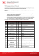
9.4. Other Commands Access via PC_to_RDR_XfrBlock 9.4.1. GET_READER_INFORMATION This command returns relevant information about the particular ACR38x (CCID) model and the current operating status, such as, the firmware revision number, the maximum data length of a command and response, the supported card types, and whether a card is inserted and powered up or not. Note: This command can only be used after the logical smart card reader communication has been established using the SCardConnect() API.
Appendix A. Supported Card Types The following table summarizes the card type returned by GET_READER_INFORMATION correspond with the respective card type.
Appendix B.