
User guide


ACR83 – Reference Manual info@acs.com.hk
Version 1.05
www.acs.com.hk
Page 16 of 49
bMsgIndex:
00h: LCD will display “Enter PIN:”
Any other values will raise an error.
If the data structure format error, the ACR83 will give “6B 80h.”
For the system unit is bit (bmFormatString bit 7=0). The APDU formatting is total different with system
unit is byte (bmFormatString bit 7=1).
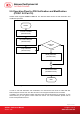
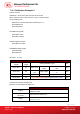
11.1. Error Checking (Bit)
Verification system unit is bit.
Command Header
SpePINLen
APDU Command
Header
APDU
Length
Offset SpePINPos PIN
CLA INS P1 P2 Lc
Offset
SpePINLenPos
SpePINSize
Not used
field/may not exist
PIN
Check points in implementing the PIN Verification Data Structure:
• SpePINLen must be equal to Lc
• SpePINPos must be equal or larger than SpePINLenPos + SpePINSize
• SpePINLen – SpePINPos must be larger or equal to SpePinMax (if BCD, need multiple 4)
• SpePinMax must be equal or larger than SpePinMin
• SpePinMax cannot be larger than 16 digits because LCD one row only have 16 digits
• SpePinMin must be equal or larger than 1
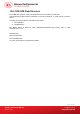
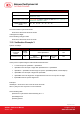
11.2. Error Checking (Byte)
Check points in implementing the PIN Verification Data Structure:
• Lc must equal to SpePINLen + SpePINPos
• SpePINPos must be equal or larger than SpePINLenPos + SpePINSize
• SpePINLen – SpePINPos must be larger or equal to SpePinMax (if BCD, need multiple 4)
• SpePinMax must be equal or larger than SpePinMin
• SpePinMax cannot be larger than 16 digits because LCD one row only have 16 digits
• SpePinMin must be equal or larger than 1
Verification system unit is byte.
Command Header Offset SpePINPos
SpePINLen
APDU Command
Header
APDU
Length
Offset SpePINPos PIN
CLA INS P1 P2
Lc
Offset
SpePINLenPos
SpePINSize
Not used
field
PIN