
User guide


ACR83 – Reference Manual info@acs.com.hk
Version 1.05
www.acs.com.hk
Page 20 of 49
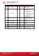
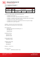
PIN (bits)
Input PIN 0 0010 0100 0110 1000 101
Result PIN
0 0010 0100 0110 1000 1010 0011 0000 0011 0000 0011
0000 0011 0000
Result APDU in bit format
0101 0101 0110 0010 0100 0110 1000 1010 0011 0000 0011
0000 0011 0000 0011 0000
Result APDU in byte
format
55 62 46 8A 30 30 30 30
The whole APDU in byte format will be:
00 20 00 01 08 55 62 46 8A 30 30 30 30h
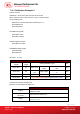
If arrangement is Right:
bmFormatString change to=5Dh
00 20 00 01 08 55 65 30 30 30 31 23 45h
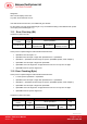
11.5. Verification Example 3
System unit is Byte.
Command Header Offset SpePINPos
SpePINLen
APDU
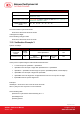
Command
Header
APDU
Length
Offset SpePINPos PIN
CLA INS P1 P2 Lc
Offset
SpePINLenPos
SpePINSize
Not used
field
PIN
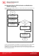
Check points in implementing the PIN Verification Data Structure:
• Lc must be equal to SpePINLen + SpePINPos
• SpePINPos must be equal or larger than SpePINLenPos + SpePINSize
• SpePINLen – SpePINPos must be larger or equal to SpePinMax(if BCD, need multiple 4)
• SpePinMax must be equal or larger than SpePinMin
• SpePinMax cannot be larger than 16 digits because LCD one row only have 16 digits
• SpePinMin must be equal or larger than 1
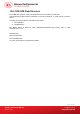
Example1:
abPINApdu = 00 20 00 01 09 57 30 30 30 30 30 30 30 30h
After Lc (09h), the first 1 byte 57h is control character.
bmFormatString=89h
SpePinPos=1 byte because bmFormatString bit 7 = 1
SpeLeftRight=Left
SpePINTyp=BCD