Version 1.5 11-2005 Unit 1008, 10th Floor, Hongkong International Trade and Exhibition Centre 1 Trademart Drive, Kowloon Bay, Hong Kong Tel: +852 2796 7873 Fax: +852 2796 1286 Email: info@acs.com.hk Website: www.acs.com.
ADT60/AET60 Reference Manual version 1.5 November 2005 Contents 1. Introduction........................................................................................................................... 3 2. Features................................................................................................................................. 3 3. Fingerprint Scanner.............................................................................................................. 4 4.
ADT60/AET60 Reference Manual 1. version 1.5 November 2005 Introduction The ACS ADT60 BioSIMKey / AET60 BioCARDKey is a device which combines a fingerprint scanner and a smart card reader/writer. The fingerprint scanner (TouchChip) makes use of the Active Capacitive-Sensing Technology from STMicroelectronics. The reader/writer part enables the communication between a computer (for example, a PC) and a smart card.
ADT60/AET60 Reference Manual 3. version 1.5 November 2005 Fingerprint Scanner BioCARDKey/BioSIMKey is built around the TouchChip Silicon fingerprint sensor. It is a fast, reliable and inexpensive fingerprint peripheral, which can be used to authenticate users of computers and all kinds of information technology devices. The TouchChip device is suitable for applications such as desktop access control, network security, Internetbased applications and commercial verification and identification systems.
ADT60/AET60 Reference Manual 4. Smart card reader 4.1 Supported Card Types version 1.5 November 2005 The BioCARDKey/BioSIMKey can operate MCU card with T=0 and T=1 protocol. The table presented in Appendix A explains which card type selection value must be specified for the various card types supported by the reader. 4.1.
ADT60/AET60 Reference Manual version 1.5 November 2005 4.2.2 Programming Voltage VPP (C6) According to ISO 7816-3, the smart card contact C6 (VPP) supplies the programming voltage to the smart card. Since all common smart cards in the market are EEPROM based and do not require the provision of an external programming voltage, the contact C6 (VPP) has been implemented as a normal control signal in the BioCARDKey/BioSIMKey.
ADT60/AET60 Reference Manual 5. version 1.5 November 2005 Power Supply The BioCARDKey/BioSIMKey requires a voltage of 5V DC, 100mA, and regulated, power supply. The BioCARDKey/BioSIMKey gets the power supply from the PC through the cable supplied along with the device. Status LEDs Red LED on the front of the reader indicate the activation status of the smart card interface: Red LED 6. Indicates power supply to the smart card is switched on, i.e., the smart card is activated.
ADT60/AET60 Reference Manual 7. version 1.5 November 2005 PC-Reader Communication protocol During normal operation, the BioCARDKey/BioSIMKey smart card reader acts as a slave with regards to the communication between a computer and the device. The communication is carried out in the form of successive command-response exchanges. The computer transmits a command to the reader and receives a response from the reader after the command has been executed.
ADT60/AET60 Reference Manual version 1.5 November 2005 7.1.2 Extended Command A command consists of six protocol bytes and a variable number of data bytes and has the following structure: byte 1 2 3 4 5 6 ... N+5 N+6 (N>0) Header Instruction Data Length = N FFH Data Checksum Data Length N Header Always 01H to indicate the start of a command. Instruction The instruction code of the command to be carried out by the BioCARDKey/BioSIMKey.
ADT60/AET60 Reference Manual 7.2 version 1.5 November 2005 Response The response from the BioCARDKey/BioSIMKey to any command depends on whether the command has been received by the reader without error (e.g., checksum error). 7.2.
ADT60/AET60 Reference Manual version 1.5 November 2005 7.2.2 No transmission error with extended response The response by the BioCARDKey/BioSIMKey to a correctly received command consists of three protocol bytes, two status bytes and a variable number of data bytes and has the following structure: byte 1 2 3 Header SW1 SW2 4 5 6 7 ... N+6 (N>0) N+7 Data Checksum Data length = N FFH Data Length N Header Always 01H to indicate the start of the response.
ADT60/AET60 Reference Manual 7.3 version 1.5 November 2005 Reset Message A reset of the reader occurs automatically whenever the reader is being powered up. A reset can also be actuated through the RS-232/USB interface.
ADT60/AET60 Reference Manual version 1.5 November 2005 Card Status Message for Card Insertion byte 1 2 3 4 5 Header SW1 SW2 Data length Checksum 01 H FF H 01 H 00 H FF H Card Status Message for Card Removal byte 1 2 3 4 5 Header SW1 SW2 Data length Checksum 01 H FF H 02 H 00 H FC H A card status message is transmitted only once for every card insertion or removal event. The reader does not expect an acknowledge signal from the computer.
ADT60/AET60 Reference Manual version 1.5 November 2005 The following example shows the transmission of a command with instruction code A2H and one data byte with the value 3DH.
ADT60/AET60 Reference Manual 8. version 1.5 November 2005 Smart Card Commands The commands executed by the BioCARDKey/BioSIMKey smart card reader can generally be divided into two categories, namely, Control Commands and Card Commands. Control Commands control the internal operation of the BioCARDKey/BioSIMKey. They do not directly affect the card inserted in the reader and are therefore independent of the selected card type.
ADT60/AET60 Reference Manual version 1.5 November 2005 byte 1 card type 2 15 14 13 12 11 10 9 8 7 6 5 4 3 2 1 0 See Appendix A for the correspondence between these bits and the respective card types. C_SEL The currently selected card type as specified in a previous SELECT_CARD_TYPE command. A value of 00H means that no card type has been selected.
ADT60/AET60 Reference Manual BAUD RATE version 1.5 November 2005 Selects the baud rate (bps) of the serial interface between reader and host system. The default hardware baud rate is 9600 bps. (Baud rate changes are only valid on RS232 reader).
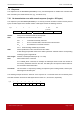
ADT60/AET60 Reference Manual version 1.5 November 2005 8.1.4 RESET This section describes the RESET command only for the case when no card type is selected or when the card type 00H is selected. For all other cases, please refer to the specific section described for each individual card type. Command format Instruction Code Data length 80 H 00 H Response data format ATR ATR The answer-to-reset string returned by the card.
ADT60/AET60 Reference Manual version 1.5 November 2005 8.1.6 SET_PPS_MODE This command selects the PPS mode to be used Command format Instruction Code Data length 07 H 01 H Data PPS_Mode NOTIFY Specifies whether the Card Status Message shall be transmitted to notify the host computer of card insertion / removal 00H : baud rate to/from the card is from 9600 bps to 115200 bps (default) 01H : baud rate to/from the card is at 9600 bps only Response data format No response data 8.
ADT60/AET60 Reference Manual version 1.5 November 2005 8.2.2 POWER_OFF This command powers off the card inserted in the card reader. Command format Instruction Code Data length 81 H 00 H Response data format No response data 8.2.3 EXCHANGE_APDU To exchange an APDU (Application Protocol Data Unit) command/response pair between the MCU card inserted in the BioCARDKey/BioSIMKey and the host computer. Command format Instruction Data Code length LEN Data CLA INS P1 P2 Lc BYTE 1 ...2 ...
ADT60/AET60 Reference Manual version 1.5 November 2005 8.2.4 EXCHANGE_T1_FRAME To exchange an APDU (Application Protocol Data Unit) command/response pair between the MCU card inserted in the BioCARDKey/BioSIMKey and the host computer using T1 protocol. Command format Instruction Code Data length Data LEN T1 BLOCK FRAME A1 H LEN Length of APDU command data, N DATA T1 Block frame to be sent to the card Response data format BYTE 1 BYTE x ... ...
ADT60/AET60 Reference Manual version 1.5 November 2005 Appendix A: Supported Card Types The following table summarizes which values must be specified in the SET_CARD_TYPE command for a particular card type to be used, and how the bits in the response to the GET_ACR_STAT command correspond with the respective card types.
ADT60/AET60 Reference Manual version 1.5 November 2005 Appendix B: Response Status Codes The following table summarizes the possible status code bytes SW1, SW2 returned by the BioCARDKey/BioSIMKey: SW1 SW2 Status 90 00 OK – command successfully executed 90 01 OK – using T=1 protocol (only in response to the RESET command) 90 10 OK – synchronous protocol is used (only in response to the RESET command). The exact card type should be selected by using the SELECT_CARD_TYPE command.
ADT60/AET60 Reference Manual version 1.5 November 2005 Appendix C: Technical Specifications Device BioCARDKey/BioSIMKey Fingerprint Scanner & Smart Card Reader/Writer Power supply Supply voltage ....................................... Regulated 5V DC Supply current ....................................... < 100mA (without smart card) Universal Serial Bus Interface Type....................................................... USB, four lines: +5V, GND, D+ and DConnector .......................................
ADT60/AET60 Reference Manual version 1.5 November 2005 Appendix D: Recommended Device Cleaning Procedures D.1 Introduction The key elements of image quality are the consistency within the actual image and the background of the image. Software algorithms are more accurate and generally faster when the image quality is consistent and the background has not changed dramatically.