
User's Manual
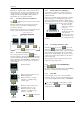

3200 Series
A
CS 3216 Operators Manual 13
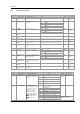
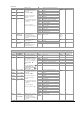
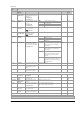
7.1.1 Master Parameter List
INPUT LIST I NPUT
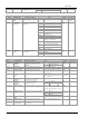
Name Scrolling Display Parameter Description Value Default Access Level
IN.TYP INPUT TYPE Selects input linearisation and range See manufacture manual for input types available
Conf
L3 R/O
none
No units - only for custom linearisation
o
C
Celsius
o
F
Fahrenheit
o
k
Kelvin
UNITS DISPLAY UNITS Display units shown on the
instrument
PErc
%
o
C
L3
nnnn
No DP
nnn.n
One DP
DEC.P DISPLAY
POINTS
Decimal point position
nn.nn
Two DP
nnnn
Conf
L3 R/O
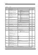
MV.HI LINEAR INPUT
HIGH
High limit for mV (mA) inputs -10.00 to +80.00mV
80.00
Conf
MV.Lo LINEAR INPUT
LOW
Low limit for mV (mA) inputs -10.00 to +80.00mV
-10.00
Conf
RNG.HI RANGE HIGH
LIMIT
Range high limit for thermocouple
RTD and mV inputs
From the high limit of the selected input type to the
‘Low Range Limit’ parameter minus one display unit.
Conf
L3 R/O
RNG.LO RANGE LOW
LIMIT
Range low limit for thermocouple
RTD and mV inputs
From the low limit of the selected input type to the
‘High Range Limit’ parameter minus one display unit.
Conf
L3 R/O
PV.OFS PV OFFSET A simple offset applied to all input
values.
Generally one decimal point more than PV
L3
FILT.T FILTER TIME Input filter time OFF to 100.0 seconds
1.6
L3
Auto
Automatic
0
o
C
Fixed at 0
o
C
CJ.typ CJC TYPE Configuration of the CJC type
50
o
C
Fixed at 50
o
C
Auto
Conf and if
T/C
L3 R/O
oFF
No sensor break will be detected
on
Open circuit sensor will be detected
SB.typ SENSOR BREAK
TYPE
Defines the action which is applied
to the control output if the sensor
breaks (open circuit).
Lat
Latching
on
Conf
L3 R/O
CJC.i n CJC
TEMPERATURE
Temperature measured at the rear
terminal block. Used in the CJC
calculation
Read only
Conf
L3 R/O and
if T/C
Pv.i n PV INPUT
VALUE
Current measured temperature Minimum display to maximum display range
Conf
L3 R/O
mv.i n MILLIVOLT
INPUT VALUE
Millivolts measured at the rear PV
Input terminals
xx.xx mV - read only
Conf
L3 R/O
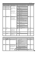
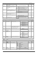
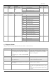
INPUT/OUTPUT LIST 1 ‘IO-1’
Name Scrolling Display Parameter Description Value Default Access Level
none
No input or output fitted
dC.OP
DC output
ReLy
Relay output
L.IO
Logic Input/Output
1..i d I/O 1 TYPE I/O channel 1 hardware type
defined by the hardware
fitted
SSR
Triac output
As
ordered
Read only
none
Disabled. If disabled no further
parameters are shown
d.out
Digital output
UP
Valve open codes VC and VP only
dwn
Valve close codes VC and VP only
Heat
Heat output
CooL
Cool output
d.in
Digital input if ‘1.i d ’ = ‘L.IO
HEAt
Conf
w.SP
Working setpoint re-transmission
PV
Process variable re-transmission
1.FUNC I/O 1 FUNCTION I/O channel function.
If the instrument is ordered
as valve positioner (codes
VC or VP), only options
available are , none,
d.out, UP, or dwn
Note: If output 1 is set to
Up ensure the other valve
position output is set to
dwn and vice versa
OP
Output power demand re-transmission
Shown if I/O 1 TYPE =
dc.OP Retransmission