
User's Manual

3200 Series
14 ACS 3216 Operators Manual
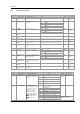
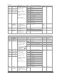
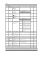
INPUT/OUTPUT LIST 1 ‘IO-1’
Name Scrolling Display Parameter Description Value Default Access Level
1.SRC.A I/O 1 SOURCE A
None
No event connected to the output
AL1
Alarm 1
1.SRC.B
I/O 1 SOURCE B
AL2
Alarm 2
AL3
Alarm 3
1.SRC.C I/O 1 SOURCE C
AL4
Alarm4
ALL.A
All alarms
nw.AL
Any new alarm
Ct.AL
CT alarm, load, leak & overcurrent
Lbr
Loop break alarm
Sbr
Sensor break alarm
t.End
Timer end status
t.run
Timer run status
mAn
Manual status
rmt.F
Remote fail
Pwr.f
Power fail
1.SRC.D I/O 1 SOURCE D
These parameters only
appear when the channel
function is a Digital output,
i.e. 1.FUNC = d.out
Selects an event status to be
connected to the output
channel.
The output status is the
result of an OR of Src A,
Src B, Src C, and Src D
Up to four events can,
therefore, operate the output
prg.e
Programmer event.
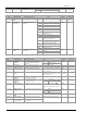
none
Conf
None
Input not used
Ac.AL
Alarm acknowledge
SP2
Setpoint 2 select
Loc.b
Front keypad disable (keylock)
t.res
Timer/programmer reset
t.run
Timer/programmer run
t.rrS
Timer/programmer run/reset. Make to
run, break to reset
t.HLd
Timer/programmer hold
Man
Manual status
Sby
Standby mode. In this mode control
outputs go to zero demand
Rmt
Remote digital setpoint select
Rec
Recipe select through IO1 digital input
UP
Remote key ‘Up’
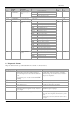
1.D.IN DIGITAL INPUT
FUNCTION
This parameter is only
applicable to I/O 1 and only
appears if the channel
function is a Digital IP
i.e. 1.FUNC = d.in
Only one function may be
activated by a physical input
Dwn
Remote key ‘Down’
Ac.AL
Conf
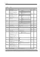
1.PLS OUTPUT 1
MINIMUM PULSE
TIME
Minimum output on/off
time.
Only applies to time
proportioning outputs and
prevents relays from
switching too rapidly
0.0 to
150.0
Auto or 1.0 to 150.0 seconds
Auto = 110mS
5.0 sec
for
relay.
Auto for
logic
Conf
1.SENS I/O 1 SENSE To configure the sense of
the input or output channel
nor
Inv
Normal
Inverted
nor
Conf
0.20
0-20mA output
1.rng DC OUTPUT
RANGE
To configure 0-20mA or 4-
20mA output
Only appears if the output
module is DC output
4.20
4-20mA output
L3
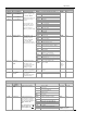
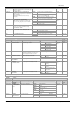
OUTPUT LIST 2 ‘op-2’
Name Scrolling
Display
Parameter Description Value Default Access Level
none
Output not fitted
rely
Relay output
L.OP
Logic output (3200 only)
dC.Op
0-20mA output.
2.i d OUTPUT 2
TYPE
Output channel 2 hardware
type
SSR
Triac output
As ordered Read only
None
Disabled. If disabled no further
parameters are shown
d.out
Digital output
UP
Valve open codes VC and VP only
Dwn
Valve close codes VC and VP only
Heat
Heat output
CooL
Cool output
d.out
Conf
w.SP
Working setpoint re-transmission
2.FUNC FUNCTION Output channel 2 function
If the instrument is ordered as
valve positioner (codes VC or
VP), only options available are
, none, d.out, UP, or
dwn
Note: If output 2 is set to Up
ensure the other valve
position output is set to dwn
PV
Process variable re-transmission
Shown if I/O 2 TYPE =
dc.OP Retransmission