
User's Manual

3200 Series
22 ACS 3216 Operators Manual
9. Digital Communications
Digital Communications (or ‘comms’ for short) allows the
controller to communicate with a PC or a networked
computer system. Digital communications is not available
in 3116 controllers.
This product conforms to MODBUS RTU ® protocol a full
description of which can be found on www.modbus.org.
Two ports are available both using MODBUS RTU
communication facilities:
1. a configuration port - intended to communicate with a
system to download the instrument parameters and to
perform manufacturing tests and calibration
2. an optional RS232 or RS485 port on terminals HD, HE
and HF - intended for field communications using, for
example, a PC running a SCADA package.
The two interfaces cannot operate at the same time.
For a full description of digital communications protocols
(ModBus RTU) refer to the 2000 series Communications
Handbook, part number HA026230, available on
www.eurotherm.co.uk.
Each parameter has its own unique ModBus address. A list
of these is given at the end of this section.
9.1 Digital Communications Wiring
9.1.1 RS232
To use RS232 the PC will be equipped with an RS232 port,
usually referred to as COM 1.
To construct a cable for RS232 operation use a three core
screened cable.
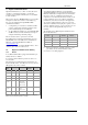
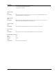
The terminals used for RS232 digital communications are
listed in the table below. Some PC's use a 25 way connector
although the 9 way is more common.
Standard
Cable
PC socket pin
no.
PC Function * Instrument
Terminal
Instrument
Colour 9 way 25 way Function
White 2 3 Receive, RX HF Transmit,
TX
Black 3 2 Transmit, TX HE Receive, RX
Red 5 7 Common HD Common
Link
together
1
4
6
6
8
11
Rec'd line sig.
detect Data
terminal ready
Data set ready
Link
together
7
8
4
5
Request to
send
Clear to send
Screen 1 Ground
* These are the functions normally assigned to socket pins.
Please check your PC manual to confirm.
9.1.2 RS485 (2-wire)
To use RS485, buffer the RS232 port of the PC with a
suitable RS232/RS485 converter. The Eurotherm Controls
KD485 Communications Adapter unit is recommended for
this purpose. The use of a RS485 board built into the
computer is not recommended since this board may not be
isolated, which may cause noise problems, and the RX
terminals may not be biased correctly for this application.
To construct a cable for RS485 operation use a screened
cable with one (RS485) twisted pair plus a separate core for
common. Although common or screen connections are not
necessary, their use will significantly improve noise
immunity.
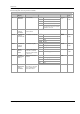
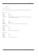
The terminals used for RS485 digital communications are
listed in the table below.
Standard Cable
Colour
PC Function * Instrument
Terminal
Instrument
Function
White Receive, RX+ HF (B) or (B+) Transmit, TX
Red Transmit, TX+ HE (A) or (A+) Receive, RX
Green Common HD Common
Screen Ground
• These are the functions normally assigned to socket
pins. Please check your PC manual to confirm .
See section 2.12 for wiring diagrams