
User's Manual


S76S
LoRa Wireless Communication Module
H
901-10201
Mar 22th ,2017
7 of 18
Product Name
Version
Doc No
Date
Page
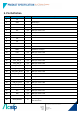
2-5-2. NRST pin characteristics
The NRST pin input driver uses CMOS technology.
It is connected to a permanent pull-up resistor (R
PU
).
The following figure is recommended NRST pin protection circuit against parasitic resets.
Symbol
Description
Conditions
Min
Typ.
Max
Unit
V
IL(NRST)
NRST input low level
voltage
VSS
0.8
V
V
IH(NRST)
NRST input high level
voltage
1.4
VDD33
V
V
OL(NRST)
NRST output low level
voltage
I
OL
= 2mA
2.7V<VDD33<3.6V
0.4
V
V
OL(NRST)
NRST output low level
voltage
I
OL
= 1.5mA
1.65V<VDD33<2.7V
0.4
V
V
hys(NRST)
NRST schmitt trigger
voltage hysteresis
10%
VDD33
mV
R
PU
Weak pull-up
Equivalent resistor
V
IN
= GND
30
45
60
K Ω
V
F
NRST Input filtered pulse
50
nS
V
NF
NRST Input not filtered
pulse
VDD33 > 2.7 V
350
nS