
Operation Manual

18
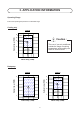
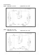
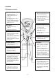
Indicator Lights
AWM / A5WM - G SERIES
IR signal receiver
When there is infrared remote control operating
signal, the signal receiver on indoor unit will made a
(beep) for signal acceptance confirmation.
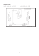
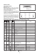
Cooling unit / Heatpump unit
The table below shows the LED indicator light for air
conditioner unit under normal operation and fault
condition. The LED indicator lights are located at the
middle of the air conditioner unit.
The heat pump units is equipped with an “auto” mode,
whereby the unit will provide reasonable room
temperature by switching the unit automatically to
either “cool” mode or “heat” mode, according to the
temperature setting set by the user.
LED Indicator Lights : Normal Operation And Faulty Indication Table
COOL/HEAT
(GREEN/RED)
Normal Operation / Fault Indication Action
/
/
/
Red
/
Green
/
/
Red
Cool mode
Heat mode
Auto mode in Heating operation
Auto mode in Cooling operation
Timer on
Sleep mode on
Ionizer on
Fan mode on
Indoor coil sensor open
Outdoor coil sensor open
Room air sensor contact Loose / Short
Call your dealer
Call your dealer
-
-
-
-
-
-
-
-
- ON
/ - ON or OFF
- Blinking
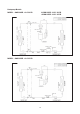
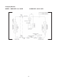
LED Indicator Lights for Cooling Unit / Heatpump
Unit
Red
Green
/
/
/
/
-
Dry mode on
1 time
3 times
1 time
Compressor overload /
Indoor coil sensor short /
Outdoor coil sensor short
3 times
5 times
6 times
Defrost operation
Gas leak
Outdoor coil sensor exist (MS mode)
Hardware error (tact switch pin short)
Call your dealer
Call your dealer
Call your dealer
Call your dealer
Call your dealer