
User's Manual


SYSTEM DESCRIPTION AND INSTALLATION MANUAL
TCAS 3000 Traffic Alert and Collision Avoidance System
34−43−23
Use or disclosure of information on this page is subject to the restrictions in the proprietary notice of this document.
Page 3−55
15 Dec 2005
W37
W38
W39
W40
W41
W42
W43
W44
W45
W46
W47
W48
W25
W26
W27
W28
W29
W30
W31
W32
W33
W34
W35
W36
W13
W14
W15
W16
W17
W18
W19
W20
W21
W22
W23
W24
W1
W2
W3
W4
W5
W6
W7
W8
W9
W10
W11
W12
W50
E8
E7
E6
E4
E3
E2
E1
W49
16
1
9
8
16
1
9
8
16
1
9
8
16
1
9
8
16
1
9
8
16
1
9
8
14
1
8
7
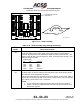
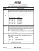
JUMPER WIRE (50 REQD)
SEE DETAIL A
DETAIL A
W1
AD−15341−R1@
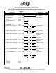
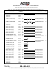
Figure 3−12. Strap Assembly
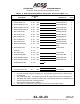
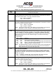
Table 3−10. Strap Assembly Programming Instructions
Strap
Number
Functional Description
W1
W2
SYSTEM (SIDE) POSITION: (B0, B1)
The System (Side) Position straps define which system position the transponder is
located at. Normal practice is to designate the captain’s or pilot’s system as Side 1, the
copilot’s system as Side 2, and the engineer’s, center, or backup system as Side 3. The
straps are defined as follows:
Strap Number
W1 W2 Definition
Gnd Gnd Side 1
Open Gnd Side 2
Gnd Open Side 3
Open Open Reserved
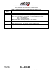
W3
W4
PARITY
The Parity straps are used to make sure the strap data is valid. Straps W3 and W4 are
parity bits and must be programmed as follows:
After all other straps have been programmed, count the number of Gnd (Uncut) straps in
positions W1, W2 and W5 thru W48. If the number of uncut straps is even, cut strap W3.
If the number of uncut straps is odd, cut strap W4.
NOTES:
1. To have correct parity, either jumper W3 or W4 has to be cut, but not both.
2. If parity is invalid, the transponder fails the Power−On Self−Test (POST) and
discontinues operation.