Refrigerating air dryer ACT 600 – 5000 Air – water cooled EN - User’s maintenance and spare parts manual 7425MUM178_EN_2012-10 CANADA
Dear Customer, thank you for choosing our product. In order to get the best performances out of this product, please read this manual carefully. To avoid incorrect operation of the equipment and possible physical risk to the operator, please read and strictly follow the instructions contained in this manual. Note, these instructions are in addition to the safety rules that apply in the country where the dryer is installed.
Contents 1 Identification plate 5 2 Warranty conditions 5 3 3.1 3.2 3.3 3.4 Safety rules Definition of the conventional signs used in this manual Warnings Proper use of the dryer Instructions for the use of pressure equipment according to PED directive 97/23/EC 6 6 7 7 8 4 4.1 4.2 4.3 4.4 4.5 4.6 4.7 4.8 4.
8.3 8.4 8.5 Spare parts Maintenance operation on the refrigeration circuit Dismantling of the dryer 37 39 39 9 Attachments Exploded views – List of components Electric diagrams – List of components 9.1 Dryers dimensions 9.1.1 ACT 600 – 1250 9.1.2 ACT 1500 – 2500 9.1.3 ACT 3000 - 3750 9.1.4 ACT 4000 – 5000 9.2 Exploded views 9.2.1 ACT 600 – 1250 Air Cooled 9.2.2 ACT 600 – 1250 Water Cooled 9.2.3 ACT 1500 – 2500 Air Cooled 9.2.4 ACT 1500 – 2500 Water Cooled 9.2.5 ACT 3000 – 3750 Air Cooled 9.2.
Identification plate 1 Identification plate The identification plate is located on the back of the dryer and shows all the primary data of the machine. This data should always be referred to when calling the manufacturer or distributor. The removal or alteration of the identification plate will void the warranty rights.
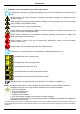
Safety rules 3 Safety rules 3.1 Definition of the conventional signs used in this manual Carefully read instruction manual before attempting any service or maintenance procedures on the dryer. Caution warning sign. Risk of danger or possibility of damage to equipment, if related text is not followed properly. Electrical hazard. Warning message indicates practices or procedures that could result in personal injury or fatality if not followed correctly. Danger hazard. Part or system under pressure.
Safety rules 3.2 Warnings Compressed air is a highly hazardous energy source. Never work on the dryer with pressure in the system. Never point the compressed air or the condensate drain outlet hoses towards anybody. The user is responsible for the proper installation of the dryer. Failure to follow instructions given in the “Installation” chapter will void the warranty. Improper installation can create dangerous situations for personnel and/or damages to the machine could occur.
Installation 3.4 Instructions for the use of pressure equipment according to PED directive 97/23/EC To ensure the safe operation of pressure equipments, the user must conform strictly to the above directive and the following: 1. The equipment must only be operated within the temperature and pressure limits stated on the manufacturer’s data nameplate. 2. Welding on heat-exchanger is not recommended. 3.
Installation 4.3 Installation site Failure to install dryer in the proper ambient conditions will affect the dryer’s ability to condense refrigerant gas. This can cause higher loads on the compressor, loss of dryer efficiency and performance, overheated condenser fan motors, electrical component failure and dryer failure due to the following: compressor loss, fan motor failure and electrical component failure. Failures of this type will affect warranty considerations.
Installation 4.4 Installation layout 1 Air compressor 2 Aftercooler 3 Condensate separator 4 Pre-Filter (min. 5 micron) 5 By-pass group 6 Dryer 7 Compressed air tank 8 Final filter 9 Condensate drain In case of heavily polluted inlet air (ISO 8573.1 class 3.-.3 or worse quality), we recommend the additional installation of a pre-filter (5 micron minimum) to prevent a clogging of the heat exchanger.
Installation 4.5 Correction factors Correction factor for operating pressure changes: Inlet air pressure psig 60 80 barg 4 5.5 Factor (F1) 0.79 0.91 120 8 1.07 140 10 1.13 160 11 1.18 180 12 1.23 203 14 1.27 Correction factor for ambient temperature changes (Air-Cooled): Ambient temperature ºF 80 90 95 100 ºC 27 32 35 38 Factor (F2) 1.11 1.09 1.06 1.00 105 40 0.94 110 43 0.87 115 45 0.78 122 50 0.
Installation 4.6 Connection to the compressed air system Operations to be performed by qualified personnel only. Never work on system under pressure. The user is responsible to ensure that the dryer will never be operated with pressure exceeding the maximum pressure rating on the unit data tag. Over-pressurizing the dryer could be dangerous for both the operator and the unit. The air temperature and the flow entering the dryer must comply within the limits stated on the data nameplate.
Installation 4.8 Electrical connections Qualified personnel should carry out connecting unit to the main power. Be sure to check the local codes in your area. Before connecting the unit to the electrical supply, verify the data nameplate for the proper electrical information. Voltage tolerance is +/- 10%. The installer is responsible for supplying and installing the power cable. Be sure to provide the proper fuses or breakers based on the data information located on the nameplate.
Start-up 4.9 Condensate drain The condensate is discharge at the system pressure. Drain line should be secured. Never point the condensate drain line towards anybody. The dryer comes already fitted with an electronic condensate drainer. Connect and properly fasten the condensate drain to a collecting plant or container. The drain cannot be connected to pressurized systems. Don’t dispose the condensate in the environment.
Start-up 5.2 First start-up This procedure should be followed on first start-up, after periods of extended shutdown or following maintenance procedures.Qualified personnel must perform the start-up. Sequence of operations (refer to paragraph 7.1 Control Panel). Ensure that all the steps of the “Installation” chapter have been observed. Ensure that the connection to the compressed air system is correct and that the piping is suitably fixed and supported.
Start-up 5.3 Start-up and shut down For short periods of inactivity, (max 2-3 days) we recommend that power is maintained to the dryer and the control panel. Otherwise, before re-starting the dryer, it is necessary to wait at least 2 hours for the compressor crankcase heater to heat the oil of the compressor. Start-up (refer to paragraph 7.1 Control Panel) Check the condenser for cleanliness (Air-Cooled). Ensure the cooling water flow and temperature is adequate (Water-Cooled).
Technical data 6 6.
Technical data 6.
Technical description 7 7.1 Technical description Control panel The control panel illustrated below is the only dryer-operator interface. reset log info ESC set T2 K T4 T3 3 PQS0047 T1 1 Main switch 2 Electronic instrument DMC24 3 Air and refrigerant flow diagram 7.2 Operation Operating principle - The dryer models described in this manual operate all on the same principle. The hot moisture laden air enters an air to air heat exchanger.
Technical description 7.3 Flow diagram (Air-Cooled) 2 T2 4 P< 12.3 12.2 P> 12.4 T3 37 P mA T4 6 36 1a 25 8 7 1 9 M 1b 12.1 T1 11 20 10 DGF0105 1c 21 13 7.4 Flow diagram (Water-Cooled) 4 2 T2 P< 12.3 12.2 12.4 T3 P> 37 P mA T4 6 36 1a 25 18 7 1 1b 19 12.1 T1 11 20 10 DGF0106 1c 21 13 1 1a 1b 1c 2 4 6 7 8 9 10 11 12.
Technical description 7.5 Refrigerating compressor The refrigerating compressor is the pump in the system, gas coming from the evaporator (low pressure side) is compressed up to the condensation pressure (high pressure side). The compressors utilized are manufactured by leading manufacturers and are designed for applications where high compression ratios and wide temperature changes are present.
Technical description 7.10 Capillary tube It consists of a piece of reduced cross section copper tubing located between the condenser and the evaporator, acting as a metering device to reduce the pressure of the refrigerant. Reduction of pressure is a design function to achieve optimum temperature reached within the evaporator: the smaller the capillary tube outlet pressure, the lower the evaporation temperature.
Technical description 7.13 Refrigerant pressure switches LPS – HPS As operation safety and protection of the dryer a series of pressure switches are installed in the gas circuit. LPS : Low-pressure protection device on the suction side of the compressor, trips if the pressure drops below the pre-set value. The values are automatically reset when the nominal conditions are restored. Calibrated pressure : R 407 C Stop 24.7 psig (1.7 barg) - Restart 53.7 psig (3.
Technical description 7.
Technical description 7.15.1 How to switch on the dryer . When the unit is powered the display shows . The condensate drain test is always active through button Press for at least 2 seconds to start the dryer: if the compressor has been shut down for enough time, it will start up immediately; otherwise the display will show the countdown of the seconds before the compressor starts up again, and the led flashes (max delay 5 minutes). ESC 7.15.
Technical description 7.15.4 How a service warning is displayed A service warning is an unusual event that must recall the attention of operators/maintenance technicians. Generally it does not stop the dryer (except for a high DewPoint parameter that can be set to stop the dryer). When the service warning is active the led flashes. If the service warning is memorized (it tripped but is lighted.
Technical description 7.15.5 How an alarm is displayed The alarm is an unusual event that always causes the dryer to switch OFF for the safety of the machine and the operators. When the alarm is active the led itself) led flashes. If the alarm is memorized (it tripped but then it switched off by is lighted (dryer stay OFF in any case). flashes the message When the led When the led is lighted, the message in sequence on the display. and the active alarm/s appear in sequence on the display.
Technical description 7.15.6 How to show the alarm memory – LOG Menu The log menu is the list of the last 10 alarms (only alarms, not service warning). They appear in chronological order (LIFO logic). With dryer ON or OFF and not in other menus, press log for at least 1 second to enter the log menu. (L01) on the display (first parameter of menu). Use Access to the log menu is confirmed by message and to move to following/previous (L01 … L10). Press log to show the selected log the arrows value.
Technical description 7.15.10 How to change operating parameters – SETUP Menu The setup menu can be used to change the dryer’s operating parameters. Only qualified personnel must be allowed to access to the setup menu. The manufacturer is not responsible for malfunctioning or failure due to modification to the operating parameters. info With dryer ON or OFF and not in other menus, simultaneously press buttons for at least 5 seconds to enter the setup menu.
Technical description 7.16 Electronic drainer This drain consists of a condensate accumulator where a capacitive sensor continuously checking liquid level is placed: as soon as the accumulator is filled, the sensor passes a signal to the electronic control and a diaphragm solenoid valve will open to discharge the condensate. For a complete condensate discharge the valve opening time will be adjusted exactly for each single drain operation. No condensate strainers are installed. No adjusting is required.
Maintenance, troubleshooting, spare parts and dismantling 8 Maintenance, troubleshooting, spare parts and dismantling 8.1 Checks and maintenance Only qualified personnel should perform troubleshooting and or maintenance operations. Prior to performing any maintenance or service, be sure that : no part of the machine is powered and that it cannot be connected to the mains supply. no part of the machine is under pressure and that it cannot be connected to the compressed air system.
Maintenance, troubleshooting, spare parts and dismantling 8.2 Troubleshooting Only qualified personnel should perform troubleshooting and or maintenance operations. Prior to performing any maintenance or service, be sure that : no part of the machine is powered and that it cannot be connected to the mains supply. no part of the machine is under pressure and that it cannot be connected to the compressed air system.
Maintenance, troubleshooting, spare parts and dismantling SYMPTOM POSSIBLE CAUSE - SUGGESTED ACTION Dew Point too low The fan is always on – verify the correct operation of the fan power contactor (see KV1/KV2 on the electric diagram) and/or of pressure transducer (see BHP on the electric diagram) – (Air-Cooled). Ambient temperature is too low - restore nominal conditions (Air-Cooled). The hot gas by-pass valve is out of setting - contact a refrigeration engineer to restore nominal setting.
Maintenance, troubleshooting, spare parts and dismantling SYMPTOM POSSIBLE CAUSE - SUGGESTED ACTION Compressor discharge temperature too high. 1. 2. 3. Condensing pressure too high Check which of the following has caused the failure : 1. The ambient temperature is too high or the room aeration is insufficient - provide proper ventilation (Air-Cooled). 2. The condenser unit is dirty - clean it (Air-Cooled). 3. The fan doesn’t work - see specific point (Air-Cooled). 4.
Maintenance, troubleshooting, spare parts and dismantling SYMPTOM Electronic instrument DMC24 is The led on or flashes. POSSIBLE CAUSE - SUGGESTED ACTION With led flashing : one or more alarms are active and the display shows and the active alarms. led lighted : one or more alarms are waiting to be reset and the display With shows and the alarms that are no longer active but not yet reset. The alarms are displayed with the following messages : 1.
Maintenance, troubleshooting, spare parts and dismantling SYMPTOM Electronic instrument DMC24 is The led on or flashes. POSSIBLE CAUSE - SUGGESTED ACTION With led flashing: one or more service warnings are active. led lighted: one or more service warnings are waiting to be reset. The With display shows the DewPoint temperature and the active or not reset service warning. The service warnings are displayed with the following messages : 1.
Maintenance, troubleshooting, spare parts and dismantling 8.3 Spare parts The suggested spare parts list will enable you to promptly intervene in case of abnormal operation, so avoiding to wait for the spares delivery. In case of failure of other parts, for example inside the refrigerating circuit, the replacement must be worked out by a refrigerating systems specialist or in our factory.
Maintenance, troubleshooting, spare parts and dismantling 38 – EN ACT 600 – 5000
Maintenance, troubleshooting, spare parts and dismantling 8.4 Maintenance operation on the refrigeration circuit Maintenance and service on refrigerating systems must be carried out only by certified refrigerating engineers only, according to local rules. All the refrigerant of the system must be recovered for its recycling, reclamation or destruction. Do not dispose the refrigerant fluid in the environment. This dryer comes ready to operate and filled with R407C type refrigerant fluid.
Attachments 9 Attachments Exploded views – List of components 1 1.
Attachments 9.1 9.1.
Attachments 9.1.
Attachments 9.1.
Attachments 9.1.
Attachments 9.2 9.2.
Attachments 9.2.
Attachments 9.2.
Attachments 9.2.
Attachments 9.2.
Attachments 9.2.
Attachments 9.2.
Attachments 9.2.
ACT 600 – 5000 (1) With Auto-Transformer TR installed QS TR 2 Q1 [2-1] KC1 V 4 3 6 5 W MC1 M 3 U 2 1 3 [2-6] [2-6] 11 12 14 L1 L2 L3 U1 V1 W1 RPP 4 TK MV1 [2-7] TK M 3 W2 U2 V2 [2-3] KV2 2 1 4 3 5 6 5 [2-2] KV1 2 1 4 3 6 6 5 FU3 FU4 A FU1-2 8 B [2-1] KC1 RC 12 11 TF 9 Sheet 01 of 03 01 Note : Rev. Drawing no. : FRACT-Q5478QCD001 Technical modifications are subject to change without notice; errors not excluded. 7 9.3.
B A 14 12 24 22 21 11 [2-1] [2-4] 1 3 5 11 [1-9] 27 BT1 DEWPOINT TEMP. 2 [1-3] 4 [1-3] 6 [1-3] 12 A2 A2 24 A1 [2-0] KHP 21 9 K 28 KC1 A 13 29 A1 15 14 mA P BHP KHP P HPS AIR IN TEMP. NU 24 2 [1-6] 4 [1-6] 6 [1-6] 12 A2 KV1 A1 I 12 25 BT2 BT3 1 3 5 11 26 2 A1 II 11 22 NU 2 [1-5] 4 [1-5] 6 [1-5] 12 A2 KV2 1 3 5 11 23 BT4 3 21 T 10 [2-0] KHP 20 14 11 4 8 ZL P 7 19 LPS 5 A [1-4] RPP Q1 [1-3] 2.3 2.4 L N 3.1 3.2 3.1 3.
– EN UKK 5 ELD UKK 5 00 10 RC1 RC2 024 00 DR1 DR2 CDI DI5 9 10 11 12 13 14 UDT 00 7 8 2 RC CBC.4 L1 L2 L3 R S T 1 MV1 TERMINAL LPS 024 12 1 2 WIRE HPS CDI DI2 3 4 TERMINAL TYPE CDI DI4 5 6 0 HIGH PRESSURE SWITCH LOW PRESSURE SWITCH FAN THERMAL PROTECTION AIR COOLED ONLY - JUMP IF NOT INSTALLED ELECTRONIC LEVEL DRAINER COMPRESSOR CRANKCASE HEATER 3 FROM TR TANSFORMER - 460V SIDE ACT 600 – 5000 4 5 6 Sheet 03 01 Note : Rev. 9 Drawing no.
– EN (*) See dryer nameplate (1) With Auto-Transformer TR installed 1 QS TR 2 [2-1] KC1 QC1 4 3 6 5 W/T3 MC1 M 3 U/T1 V/T2 2 1 3 [2-6] [2-6] 11 12 14 L1 L2 L3 4 RPP MV2 MV1 [2-1] KV0 5 U1 V1 W1 U1 V1 W1 M TK TK [2-8] TK M 3 [2-7] TK 3 [2-3] W2 U2 V2 W2 U2 V2 KV2 QV1 6 [2-2] KV1 FU3 FU4 A FU1-2 8 B [2-1] KC1 RC 12 11 TF 9 Sheet 01 of 04 01 Note : Rev. Drawing no.
ACT 600 – 5000 [2-4] 21 [2-1] 1 3 5 11 N.U. 2 [1-5] 4 [1-5] 6 [1-5] 12 1 3 5 11 2 [1-9] 25 I A1 12 23 1 3 5 11 N.U. 22 BT4 2 [1-7] 4 [1-7] 6 [1-7] 12 A2 KV1 24 BT2 BT3 2 [1-3] 4 [1-3] 6 [1-3] 12 A2 A2 11 A2 14 12 24 22 A1 24 21 9 K 26 KC1 [2-0] KHP 27 A1 28 KV0 A 13 29 BT1 A1 15 14 mA P BHP DEWPOINT TEMP. KHP P HPS 1 AIR IN TEMP. 3 1 3 5 11 N.U.
– EN B [2-5] 11 14 1.3 3.2 3.1 N L 1 [2-8] 2.4 2.3 ELD1 [2-5] KDR 2 22 24 1.3 3.2 3.1 3 1.2 1.1 [2-8] 2.4 2.3 ELD2 4 5 6 8 9 Sheet 03 of 04 01 Note : Rev. Drawing no. : FRACT-Q5478QCD002 Technical modifications are subject to change without notice; errors not excluded. 7 9.3.
– EN UKK 5 1 MV1 TERMINAL LPS 024 12 1 2 WIRE HPS CDI DI2 3 4 TERMINAL TYPE 35 5 6 DI4 ELD2 024 00 31 32 CDI 11 12 13 14 15 16 UDT 00 9 10 3 024 00 33 34 DI5 17 18 19 20 21 22 2 00 10 RC1 RC2 ELD1 MV2 7 8 L1 L2 L3 R S T RC COMPRESSOR CRANKCASE HEATER 0 HIGH PRESSURE SWITCH LOW PRESSURE SWITCH FAN THERMAL PROTECTION AIR COOLED ONLY - JUMP IF NOT INSTALLED FAN THERMAL PROTECTION AIR COOLED ONLY - JUMP IF NOT INSTALLED ELECTRONIC LEVEL DRAINER ELECTRONIC LEVEL DRAINER
– EN (1) With Auto-Transformer TR installed (*) See dryer nameplate 1 QS TR 2 [3-2] KC1 QC1 4 3 6 5 U/T1 V/T2 M 3 [3-6] 11 12 14 L1 L2 L3 RPP MC1 TK [3-6] 4 [3-6] TK M 3 U/T1 V/T2 W/T3 2 1 3 W/T3 [3-6] L N S1 S2 M1 M2 L1 L2 L3 5 6 01 of RC Note : Sheet 06 00 B 12 11 [2-0] Rev. A [3-2] KC1 TF 9 Drawing no. : FU3 FU4 FU1-2 8 FRACT-UQ5478QCD003 7 9.3.8 3/460V/60Hz+PE (*) OR 3/575V/60Hz+PE (*) (1) FUSE MAX 63 A RCD Id 0.
[1-9] 0 ACT 600 – 5000 MV2 U1 V1 W1 U1 V1 W1 M TK TK [3-7] TK M 3 [3-7] TK 3 [3-3] W2 U2 V2 W2 U2 V2 KV2 QV1 2 [3-7] [3-2] KV1 3 MV4 MV3 4 U1 V1 W1 U1 V1 W1 TK TK [3-8] TK 3 M [3-8] TK M 3 W2 U2 V2 W2 U2 V2 5 6 Sheet of 06 00 Note : Rev. 02 9 Drawing no. : 8 FRACT-UQ5478QCD003 7 9.3.
B A 21 [3-2] 1 3 5 11 N.U. 2 [2-1] 4 [2-1] 6 [2-1] 12 1 3 5 11 2 COMPRES. SUCTION TEMP. [1-9] 25 I A1 12 23 1 3 5 11 N.U. 22 BT4 COMPRES. DISCHARGE TEMP. 2 [2-3] 4 [2-3] 6 [2-3] 12 A2 KV1 24 BT2 BT3 AIR IN TEMP. 2 [1-3] 4 [1-3] 6 [1-3] 12 A2 A2 11 A2 14 12 24 22 A1 24 21 9 K 26 KC1 [2-0] KHP 27 A1 [3-4] 28 KV0 A 13 29 A1 15 14 mA P BT1 BHP KHP P HPS 1 CONDENSING PRESS. 62 – EN DEWPOINT TEMP. 0 A1 II 11 21 N.U.
ACT 600 – 5000 B [3-5] KDR A 0 5 9 1.3 3.2 3.1 N L 1 [3-8] 2.4 2.3 ELD1 [3-5] KDR 2 6 10 1.3 3.2 3.1 3 1.2 1.1 2.4 2.3 ELD2 4 [3-5] KDR 7 11 5 1.3 3.2 3.1 N L 2.4 2.3 6 ELD3 [3-5] KDR 2.4 ELD4 Note : Sheet 04 of 06 00 1.2 2.3 Rev. 3.2 1.1 9 Drawing no. : 1.3 3.1 8 [3-8] FRACT-UQ5478QCD003 8 12 7 Attachments 9.3.
ACT 600 – 5000 MC1 MV1 TERMINAL LPS 024 12 1 2 WIRE HPS CDI DI2 3 4 TERMINAL TYPE 15 DI3 5 6 7 8 UKK 5 35 DI4 ELD4 ELD3 ELD2 024 00 43 44 23 24 25 26 27 28 024 00 41 42 CDI 17 18 19 20 21 22 UDT 00 15 16 4 024 00 45 46 29 30 31 32 33 34 3 024 00 47 48 DI5 35 36 37 38 39 40 ELD1 MV4 MV3 MV2 9 10 11 12 13 14 00 10 RC1 RC2 2 AIR COOLED ONLY - JUMP IF NOT INSTALLED FAN THERMAL PROTECTION 1 AIR COOLED ONLY - JUMP IF NOT INSTALLED FAN THERMAL PROTECTION 5 6 RC UKK 5 S
Attachments 06 00 Sheet Note : 0 1 2 3 4 5 6 7 8 06 9 of Rev. Drawing no. : FRACT-UQ5478QCD003 9.3.
Blank pages 10 Blank pages 66 – EN ACT 600 – 5000
Blank pages ACT 600 – 5000 67 – EN
Original instructions are in ENGLISH - Subject to technical changes without prior notice; errors not excluded