ACTentry V-IP Operating & Installation Instructions 18-00082 Rev 3.
This manual refers to ACTentry V-IP, a TCP/IP based door videophone system. Access Control Technology Ltd. reserve the right to change the contents of this manual and the system it applies to without prior notice. While every effort has been taken by ACT to ensure the accuracy of the information contained within this document, ACT assumes no responsibility for any errors or omissions. No liability is assumed for damages resulting from the use of information contained within this document.
ACTentry V-IP Operating and Installation Manual Table of Contents Table of Contents.................................................................................................. 2 Ordering Information ............................................................................................. 3 Product Specification ..................................................................................... 3 1.0 INTRODUCTION ..................................................................................
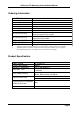
ACTentry V-IP Operating and Installation Manual Ordering Information ACT Product Code ACTentry V-IP SK ACTentry V-IP FK ACTentry V-IP SP ACTentry V-IP FP ACTentry V-IP SKX ACTentry V-IP FKX ACTentry V-IP SPX ACTentry V-IP FPX ACTentry V-IP CTR ACTentry V-IP PCH ACTentry V-IP PSU * ** Product description Surface Mount Kit* Flush Mount Kit* VoIP Door Entry Panel (surface ) VoIP Door Entry Panel (flush ) Surface Mount Kit** Flush Mount Kit** VoIP Door Entry Panel (surface) with cut out for panel mount proxim
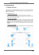
ACTentry V-IP Operating and Installation Manual 1.0 INTRODUCTION 1.1 System Overview The ACTentry V-IP (Video/audio over IP) system is a TCP/IP based videodoorphone system. Access to the building can be administered from any PC on the TCP/IP network. The system consists of: 1. ACTentry V-IP Door Panel: The door panel has a Call button, colour video camera and audio unit. Note: The extended versions of the entry panel has a cut out for an ACT 1030 panel mount proximity reader. 2.
ACTentry V-IP Operating and Installation Manual 2.0 INSTALLATION 2.1 System Requirements The minimum PC requirements are: 1. Colour SVGA monitor with at least 800x600 screen resolution 2. Mouse and keyboard 3. CDROM drive (required during installation only) 4. Ethernet or FastEthernet LAN connection with TCP/IP protocol (100MBps preferable) 5. Operating systems: Windows 7, Windows Vista (32bit and 64bit) 6. 32-bit or 64bit processor, 1GBytes RAM, 16GB hard disk space. 7.
ACTentry V-IP Operating and Installation Manual 2.
ACTentry V-IP Operating and Installation Manual The ACTentry V-IP door panel is available in Flush-mount or Surface-Mount versions. 1.
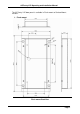
ACTentry V-IP Operating and Installation Manual The flush-mount version comprises of two parts: 1. Flush mount back box 2. Flush mount plate The flush mount back box (previous page) should be sunk into the mounting surface. Ensure to mount it at a height where the camera lens will match eye level. The flush-mount back box can be fixed to the wall via the screw holes provided by the side flaps or the back surface.
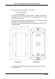
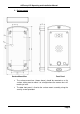
ACTentry V-IP Operating and Installation Manual 2. Surface mount Surface Mount Box Front Panel The surface mount box (shown above) should be mounted on a flat surface, taking care to mount it at a height where the camera lens will match eye level. The door front panel is fixed to the surface mount assembly using the security screws provided.
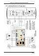
ACTentry V-IP Operating and Installation Manual 2.3 Installing the ACTentry V-IP Unit Please follow the guidelines below when installing the ACTentry V-IP unit: 1. The ACTentry V-IP controller unit should be mounted in a secure area close to a TCP/IP network connection point. 2. The recommended maximum distance between the ACTentry panel and the V-IP controller unit is 50m using CAT5 cable (or equivalent) 3.
ACTentry V-IP Operating and Installation Manual 1. When the red LINK LED and the green TX/RX LED flash slowly (about once per second), the ACTentry V-IP controller unit is powered but not connected to the network. 2. When the red LINK LED is on, the ACTentry V-IP is successfully connected to the network. 3. The green TX/RX LED beside the LAN indicates data transmission between the network and the device. 2.5 ACT handset and PC speaker connection 1.
ACTentry V-IP Operating and Installation Manual 2.7 ACTentry V-IP software installation The V-IP unit needs to be powered up and connected to the network before proceeding with the installation. ACTentry V-IP software is designed to operate on a PC connected to a TCP/IP Local Area Network. The ACTentry V-IP software should be installed on any PC where the user is expected to answer calls from the door and allow access to the building.
ACTentry V-IP Operating and Installation Manual A list of available ACTentry V-IP units on the network (LAN) will be displayed. e. “Tick” the units to be monitored by the ACTentry V-IP software. f. Click the “Apply” button to save changes. An icon representing the V-IP unit will appear on the left column. g. Click the icon for each ACTentry V-IP unit and press the “Connect” button to get live audio and video from the unit. h.
ACTentry V-IP Operating and Installation Manual 2.9 Configure Settings a. Click Setup button to configure the settings for the selected V-IP unit.
ACTentry V-IP Operating and Installation Manual Door Name: This is the name that will appear on the application and in reports. By default it is the IP address of the V-IP. A more user friendly name (e.g. Front Door) may be entered here. Door Open Time: This option specifies the length of time the Door Lock remains open before it closes and locks the door again. This should be set to a value that allows for all expected scenarios. By default it is set to 5 seconds.
ACTentry V-IP Operating and Installation Manual b. Click on Audio Tab to configure the Audio settings in the PC. To help configure the audio properties, a second person is required at the door V-IP panel. Check that the person at the door can be heard from the PC speakers or the PC handset. PC Speaker: When the call button is pressed, the call sound should be heard over the PC speakers. Set the volume level with the slider.
ACTentry V-IP Operating and Installation Manual 3.0 OPERATION When the call button at the ACTentry V-IP entry panel is pressed, the ACTentry software will immediately pop-up a notification at the bottom right of the monitor. When the “Pop-Up Delay” is longer than 0 seconds the ACTentry V-IP software will wait for the delay time before popping up the notification unless the call is answered by another operator. Click Answer button and the video from the door will pop up on-screen.
ACTentry V-IP Operating and Installation Manual 4.0 TROUBLESHOOTING 4.1 No V-IPs found on the network Check that all V-IP units are powered up and connected to the Local Area Network. On the V-IP unit, check the red LINK LED is on. Check the network settings under Settings on the top right. Choose the correct Network Adapter on the machine.
ACTentry V-IP Operating and Installation Manual 4.2 Audio Feedback is heard by PC user when connected to live video Lift the ACT Handset and listen. Go to the Audio Settings and decrease the microphone sensitivity and speaker volumes. The feedback should now be gone. Increase the volume settings for the speaker and microphone in small adjustments until satisfactory volume levels are received in both, making sure no feedback occurs. Tick the Push-To-Talk option under Audio tab. 4.
ACTentry V-IP Operating and Installation Manual 4.4 The person at the door cannot hear PC User Increase the Microphone sensitivity in Audio Settings. Also check the following: 1. Ensure that the Speaker Grill is fitted securely against the Door Entry Panel Grill. 2. Check the Door Entry Panel Grill for any blockages. 3. Check that the supply voltage is not at an inadequate level. For best operation it should be between 10V and 15V between terminals marked + and -12V on the speech unit. 4.
ACTentry V-IP Operating and Installation Manual 4.5 Video picture is poor quality or grainy The bandwidth can be increased. Go to Settings in the ACTentry V-IP application and select bandwidth of 1024Kb/s. Also check the video signal and 0V are on the same twisted pair. 4.6 Call Button not making call when pressed Check the V-IP plays a sound when call button pressed. If not check the call button wiring. One call button wire should connect to the CALL input on the ACTentry V-IP unit.
ACTentry V-IP Operating and Installation Manual 5.0 SETTING A FIXED IP ADDRESS By default the V-IP unit is supplied with support for DHCP server only. The IP address is assigned by the server when the device powers up. In some circumstances it might be necessary to fix the IP address of the V-IP unit. The application „Telnet‟ is used to configure a fixed IP address. (Note: Telnet is not available on Vista machines).
ACTentry V-IP Operating and Installation Manual If the V-IP unit does not have a known IP address, then it can be set to a default value by doing the following: 1. Power up the unit 2. Remove Link J9 (near the CALL connection on the board) 3. LED DS1 (first LED on daughter card) flashes 4. Hold down the tamper switch for 3 seconds 5. LED DS1 stays on 6. Replace Link J9 7. LED DS3 (third LED) flashes 8. Power down the unit. 9. Power up the unit. 10. IP address now set to 192.168.1.66 11.
ACTentry V-IP Operating and Installation Manual 6.
ACTentry V-IP Operating and Installation Manual 7.0 Installation Notice for Flush mount units.
ACTentry V-IP Operating and Installation Manual 8.0 Mounting instructions for Extended Version of ACTentry V-IP. The ACTentry V-IP door panel is available in Flush-mount or Surface-Mount versions with a cut out for panel mount readers. 8.
ACTentry V-IP Operating and Installation Manual The flush-mount version comprises of two parts: 1. Flush mount back box 2. Flush mount plate The flush mount back box (shown above) should be sunk into the mounting surface. Ensure to mount it at a height where the camera lens will match eye level. The flush-mount back box can be fixed to the wall via the screw holes provided by the side flaps or the back surface.
ACTentry V-IP Operating and Installation Manual 8.2 ACTentry V-IP SPX – Surface mount panel with cut out for panel mount reader Surface Mount Box Front Panel The surface mount box (shown above) should be mounted on a flat surface, taking care to mount it at a height where the camera lens will match eye level. The door front panel is fixed to the surface mount assembly using the security screws provided.
ACTentry V-IP Operating and Installation Manual Ordering Information: ACT Product Code ACTentry V-IP SK ACTentry V-IP FK ACTentry V-IP SP ACTentry V-IP FP ACTentry V-IP SKX ACTentry V-IP FKX ACTentry V-IP SPX ACTentry V-IP FPX ACTentry V-IP CTR ACTentry V-IP PCH ACTentry V-IP PSU Product description Surface Mount Kit* Flush Mount Kit* VoIP Door Entry Panel (surface ) VoIP Door Entry Panel (flush ) Surface Mount Kit** Flush Mount Kit** VoIP Door Entry Panel (surface) with cut out for panel mount proximity