A4x Bullet Camera Series Hardware Manual A44, A45, A46, A48, A421, A425 Ver.
Hardware Manual Table of Contents Precautions 3 Safety Instructions ........................................................................... 5 Introduction 6 List of Models.................................................................................... 6 Package Contents............................................................................. 7 Physical Description ........................................................................ 8 Mounting Options ...................................
Hardware Manual Precautions Read these instructions You should read all the safety and operating instructions before using this product. Heed all warnings You must adhere to all the warnings on the product and in the instruction manual. Failure to follow the safety instruction given may directly endanger people, cause damage to the system or to other equipment. Servicing Do not attempt to service this video device yourself as opening or removing covers may expose you to dangerous voltage or other hazards.
Hardware Manual Federal Communications Commission Statement This device complies with Part 15 of the FCC Rules. Operation is subject to the following two conditions: 1. This device may not cause harmful interference. 2. This device must accept any interference received, including interference that may cause undesired operation. Note: This equipment has been tested and found to comply with the limits for a Class A digital device, pursuant to Part 15 of the FCC Rules.
Hardware Manual Safety Instructions Cleaning Disconnect this video product from the power supply before cleaning. Attachments Do not use attachments not recommended by the video product manufacturer as they may cause hazards. Water and Moisture Do not use this video product near water, for example, near a bathtub, washbowl, kitchen sink, or laundry tub, in a wet basement, or near a swimming pool and the like.
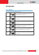
Hardware Manual Introduction List of Models This hardware manual contains the following models: A44 A45 A46 A48 A421 A425 12MP Video Analytics Zoom Bullet with D/N, Adaptive IR, Extreme WDR, SLLS, 3x Zoom lens 2MP Zoom Bullet with D/N, Adaptive IR, Extreme WDR, ELLS, 4.
Hardware Manual Package Contents Camera Mounting Screw Kit Drill Template Quick Installation Guide & Warranty Card Hex Wrench Cable Gland (for A45, A46, A421 only) WARRANTY CARD Drill Template DI/DO Terminal Block (A44, A48) NOTE: For other models, the terminal block comes connected to the DIO port of the camera 7 www.acti.
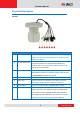
Hardware Manual Physical Description A44, A48 Item 1 Audio Output Description This jack connects to an audio output device, such as a speaker. See How to Connect Audio Input / Output Devices (Optional) on page 17. 2 DC 12V Power Input Connects the camera to an external power adapter (not included). See Connecting a Power Adapter (Optional) on page 17 for more information. 3 Reset Button Restores the factory default settings of the camera, including the administrator’s password.
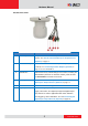
Hardware Manual A45, A46, A421, A425 Item 1 Audio Output Description This jack connects to an audio output device, such as a speaker. See How to Connect Audio Input / Output Devices (Optional) on page 17. 2 DC 12V Power Input Connects the camera to an external power adapter (not included). See Connecting a Power Adapter (Optional) on page 17 for more information. 3 Reset Button Restores the factory default settings of the camera, including the administrator’s password.
Hardware Manual Mounting Options There are several mounting options that you can use to install the camera. Select the most suitable solution for your installation environment. Mount Types Accessories Wall Suitable when mounting the camera directly on walls using the integrated bracket. See Installation Procedures on page 11. Ceiling Suitable when mounting the camera directly on walls using the integrated bracket. See Installation Procedures on page 11.
Hardware Manual Installation Procedures This section describes the procedures in installing the camera on a flat surface such as a hard or dropped ceiling and straight or tilted walls. Before installation, make sure the wall or ceiling can bear more than the weight of the camera. Step 1: Prepare for Installation 1. If a memory card will be used, install the card first before mounting the camera. 2. Attach the supplied drill template sticker on the surface. 3.
Hardware Manual Step 2: Mount the Camera 1. Mount the camera to the surface using the four (4) supplied screws. 2. Adjust the camera installation angle and orientation, and then tighten the locks crews to fix its position. 12 www.acti.
Hardware Manual Step 3: Waterproof and Connect the Cable(s) The camera and the pre-installed network cable, “pigtail”, are resistant to salt, water, weak acid, alcohol, oil, grease and other common solvents. However, users must ensure that the cable connection and the network side cable itself are also protected from different environmental factors. The camera also supports DC12V power input, Digital Input and Output (DI/DO) and Audio Input and Output devices using the bundled terminal blocks.
Hardware Manual A45, A46, A421, A425 This section describes how to waterproof the Ethernet cable of A45, A46 and A421 models using the bundled cable gland. Before connection, prepare an exterior-grade Ethernet cable with RJ-45 connector but without sleeves. NOTE: The images below are for reference only. The color or actual cable may slightly vary. Perform the following to waterproof the “pigtail” using the cable gland: 1. Attach the washer to the Ethernet connector of the camera. 2.
Hardware Manual 3. Insert the clamping nut into the Ethernet cable. 4. Insert the sealing insert through the Ethernet cable. 5. Insert the cable through the gland body. 6. Push the sealing insert into the gland body. 15 www.acti.
Hardware Manual 7. Connect the RJ-45 connector to the camera connector. 8. Attach the gland body to the camera connector. 9. Attach the clamping nut to the gland body to complete the cable solution. NOTE: Make sure the clamping nut is tightly attached to the cable gland body and the sealing insert is squeezed tightly. DISCLAIMER: ACTi will not be responsible for camera damage caused by water entering the cable connections. 16 www.acti.
Hardware Manual Connecting a Power Adapter (Optional) The camera can be powered by a Power over Ethernet (PoE) switch that is IEEE802.3af compliant. In case of using a non-PoE switch or your PoE switch has a limited power supply, you can purchase a power adapter and directly connect the camera to a power outlet. NOTE: • The power adapter is not bundled in the package.
Hardware Manual Connecting the Digital Input / Output Devices (Optional) Depending on your surveillance needs, you may connect digital input / output or audio input / output devices to your camera. The camera comes with one (1) terminal block for both digital and audio input/output devices. Digital Input (DI) devices can be used to notify the camera about an activity in the camera site. DI can be triggers of events.
Hardware Manual Step 4: Connect to Network Connect the other end of the network cable to a switch or injector. Then, connect the switch or injector to a network, PC, and a power source. See Power-over-Ethernet (PoE) connection example below.
Hardware Manual Other Adjustments and Accessories How to Install / Remove the Memory Card NOTE: Supports microSDHC and microSDXC cards. How to Insert the Memory Card 1. Open the back cover. 2. Insert a memory card into the card slot with the metallic contacts facing the lens of the camera. Push the card until it clicks into place. 3. Close the back cover.
Hardware Manual Accessing the Camera Configure the IP Addresses In order to be able to communicate with the camera from your PC, both the camera and the PC have to be within the same network segment. In most cases, it means that they both should have very similar IP addresses, where only the last number of the IP address is different from each other. There are 2 different approaches to IP Address management in Local Area Networks – by DHCP Server or Manually.
Hardware Manual If you work with our cameras regularly, then there is even a better way to discover the cameras in the network – by using IP Utility. The IP Utility is a light software tool that can not only discover the cameras, but also list lots of valuable information, such as IP and MAC addresses, serial numbers, firmware versions, etc, and allows quick configuration of multiple devices at the same time. The latest IP Utility can be downloaded for free from http://www.acti.
Hardware Manual Use the default IP address of a camera: If there is no DHCP server in the given network, the user may have to assign the IP addresses to both PC and camera manually to make sure they are in the same network segment. When the camera is plugged into network and it does not detect any DHCP services, it will automatically assign itself a default IP: 192.168.0.100 Whereas the default port number would be 80.
Hardware Manual Manually adjust the IP addresses of multiple cameras: If there are more than 1 camera to be used in the same local area network and there is no DHCP server to assign unique IP addresses to each of them, all of the cameras would then have the initial IP address of 192.168.0.100, which is not a proper situation for network devices – all the IP addresses have to be different from each other.
Hardware Manual Access the Camera Now that the camera and the PC are both having their unique IP addresses and are under the same network segment, it is possible to use the Web browser of the PC to access the camera. You can use Microsoft Internet Explorer to access the camera When using Internet Explorer browser, the ActiveX control for video stream management will be downloaded from the camera directly – the user just has to accept the use of such control when prompted so.
Copyright © 2022, ACTi Corporation All Rights Reserved 7F, No. 1, Alley 20, Lane 407, Sec. 2, Ti-Ding Blvd., Neihu District, Taipei, Taiwan 114, R.O.C. TEL : +886-2-2656-2588 FAX : +886-2-2656-2599 Email: sales@acti.