
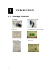
User`s manual


1-7
connector provides the interface to:
•1 transistor output - For connecting external devices such as relays
and LED:s. Connected devices can be activated by Output buttons on
the Live View page or by an Event Type. The output will show as
active (in Event Configuration > Port Status) if the alarm device is
activated.
•1 digital input - An alarm input for connecting devices that can toggle
between an open and closed circuit, for example: PIRs, door/window
contacts, glass break detectors, etc. When a signal is received the state
changes and the input becomes active (shown under Event
Configuration > Port Status).
•Auxiliary power and GND
GND Pin 1 Ground Description
Auxiliary
DC
Power
input
(not to
power
this
camera)
Pin 2 Electrically connected in parallel with the con-
nector for the power supply, this pin provides an
auxiliary connector for mains power to the unit.
This pin can also be used to power auxiliary
equipment, with a maximum current of 100mA.
Voltage: 12V DC,
Max: 1.2W
Digital
Input
Pin 3 Connect to GND to activate, or leave floating (or
unconnected) to deactivate.
Must not be exposed to
voltages greater than 30V
DC.
Transistor
Output
Pin 4 Uses an open-collector NPN transistor with the
emitter connected to the GND pin. If used with an
external relay, a diode must be connected in
parallel with the load, for protection against
voltage transients.
Max load = <100mA
Max voltage = 24V DC
(to the transistor)
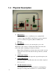
The I/O terminal pins are numbered left to right, as shown below.
Connect input/output devices to the camera as follows:
1. Attach the cables for the device securely to the supplied green connector
block.