
Hardware manual


www.acti.com
Hardware Manual
16
Prepare the DI/DO and Audio Input / Output Connector
(Optional)
Depending on your surveillance needs, you may connect digital input / output or audio input /
output devices to your camera. The camera comes with one (1) terminal block for both digital and
audio input / output devices.
How to Connect DI/DO Devices
Digital Input (DI) devices can be used to notify the camera about an activity in the camera site. DI
can be triggers of events. For example, you can connect a “panic button” to the camera; as such
when the panic button is pressed, the alarm signal will be sent through the camera. Other
common DI device applications are emergency button, smoke detector, passive infrared sensor,
etc.
Digital Output (DO) devices are external devices that are activated by the camera upon an event
inside the camera. For example, you can connect an “alarm horn” to the camera; as such when
an event occurs inside the camera (e.g. detected intruder), the alarm horn will sound. Other
common DO device applications are motion-triggered lights, electric fence, magnetic door locks,
etc.
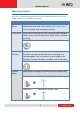
Press and hold the orange tab as you insert the wire through the pin slot, then release the orange
tab to secure the wire.
To connect digital input / output devices (DI/DO), map the pins to one of the pin combinations
below:
Device
Pin
Mapping Instructions
Digital Output
(DO)
1
DIO PW
Connect the wires of the output device to DIO PW
(Pin 1) and DO (Pin 3).
3
DO
Digital Input
(DI)
2
DIO GND
Connect the wires of the input device to DIO GND
(Pin 2) and DI (Pin 4).
4
DI
4
3
2
1
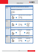
For Audio Use