Firmware User’s Manual A1D-500-V6.08.
Firmware User’s Manual V6.08.30 Table of Contents Recommended PC Specifications 5 Preparation 6 Connect the Equipment .............................................................................6 Configure the IP Addresses .......................................................................6 Access the Camera...................................................................................10 Live View 13 Login ....................................................................................
Firmware User’s Manual V6.08.30 Host............................................................................................................32 Serial Setting......................................................................................... 33 GPS Position......................................................................................... 34 Date & Time ...............................................................................................35 Network ...................................
Firmware User’s Manual V6.08.30 Save & Reboot ..................................................................................... 115 Logout ..................................................................................................... 116 Troubleshooting 117 4 www.acti.
Firmware User’s Manual V6.08.30 Recommended PC Specifications In order to configure or test the cameras, a PC with following basic specifications is needed: CPU Core 2 Duo 2.13 GHz or above Memory 2 GB or above Operating System Browser for Accessing Firmware Windows XP with SP2 or above. Windows 2003 Windows Vista Windows 2008 Windows 7 Internet Explorer 8.
Firmware User’s Manual V6.08.30 Preparation Connect the Equipment To be able to connect to the camera firmware from your PC, both the camera and the PC have to be connected to each other via Ethernet cable. At the same time, the camera has to have its own power supply. In case of PoE cameras, you can use a PoE Injector or a PoE Switch between the camera and the PC. The cameras that have the DC power connectors may be powered on by using a power adaptor.
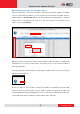
Firmware User’s Manual V6.08.30 In the example below, we successfully found D11 camera that we had just connected to the network. With the left mouse click on D11 it is possible to automatically launch the default browser of the PC with the IP address of the target camera filled in the address bar of the browser already. If you work with our cameras regularly, then there is even a better way to discover the cameras in the network – by using IP Utility.
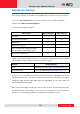
Firmware User’s Manual V6.08.30 Use the default IP address of a camera: If there is no DHCP server in the given network, the user may have to assign the IP addresses to both PC and camera manually to make sure they are in the same network segment. When the camera is plugged into network and it does not detect any DHCP services, it will automatically assign itself a default IP: 192.168.0.100 Whereas the default port number would be 80.
Firmware User’s Manual V6.08.30 Manually adjust the IP addresses of multiple cameras: If there are more than 1 camera to be used in the same local area network and there is no DHCP server to assign unique IP addresses to each of them, all of the cameras would then have the initial IP address of 192.168.0.100, which is not a proper situation for network devices – all the IP addresses have to be different from each other.
Firmware User’s Manual V6.08.30 Access the Camera Now that the camera and the PC are both having their unique IP addresses and are under the same network segment, it is possible to use the Web browser of the PC to access the camera. You can use any of the browsers to access the camera, however, the full functionality is provided only for Microsoft Internet Explorer.
Firmware User’s Manual V6.08.30 The following examples in this manual are based on Internet Explorer browser in order to cover all functions of the camera. Assuming that the camera’s IP address is 192.168.0.100, you can access it by opening the Web browser and typing the following address into Web browser’s address bar: http://192.168.0.100 Upon successful connection to the camera, the user interface called Web Configurator would appear together with the login page.
Firmware User’s Manual V6.08.30 Using IPv6 to Access the Camera The camera is IPv6-ready and has been assigned its unique static IPv6 address. The IPv6 address can be found under the System > Sytem Info menu (see System Info on page 112 for more information). To access the camera with the IPv6 address, type the IPv6 address enclosed in square brackets on the web browser address bar. For example: http://[fe80:0000:0000:0000:020f:7cff:fe0d:f711] 12 www.acti.
Firmware User’s Manual V6.08.30 Live View This section describes how to configure the IP camera. The administrator has unlimited access to all settings, while the normal user can only view live video. Login Initially there exists only administrator’s account in the camera (Account: Admin, Password: 123456) – you have to use that account to log in. You can later create normal user accounts with limited access rights if necessary.
Firmware User’s Manual V6.08.30 Live View The live view will appear automatically with the video resolution of 1280x720 (1MP cameras) or 1920x1080 (2-5MP cameras). While being on the Live View page, the Live View icon appears as being pressed: If you leave the Live View page, you can later return by pressing that button. The buttons shown on the Live View page vary depending on the functions supported by the camera.
Firmware User’s Manual V6.08.30 Notice: These digital zoom adjustments do not influence the actual video resolution of the camera. Regardless of how large or small the video appears on the display after pressing the digital zoom buttons, the actual video stream size of the camera is the same as before. You can also digitally re-scale the video to fully match the size of your display with just 1 click: - Full screen Mode You may use ESC key from the keyboard to exit the full screen mode.
Firmware User’s Manual V6.08.30 To capture the snapshots of the current live view, press the snapshot button. The snapshots are saved in Pictures folder. - Take a Snapshot Cameras with audio function have the audio controls on Live View page. - Speak to Camera To speak to the camera, press the button. If the camera is connected to a network video recorder, the audio will be recorded with the video stream.
Firmware User’s Manual V6.08.30 The digital output controls appear on the Live View page of the cameras with digital input/output function. The controls allow users to manually trigger a DO device. - Select DO Port Each DO ports are controlled separately. For cameras with more than one DO ports, select the DO port and press to set the output power level to high or to set the output power level to low.
Firmware User’s Manual V6.08.30 View Modes For Hemispheric and Fisheye cameras, the Miniature Fisheye-View and View Mode buttons appear on the Live View screen. By default, a miniature of the Fisheye view is shown on the lower right corner of the Live View, press to hide the miniature fisheye-view or to display it. You can change the viewing mode into: - ePTZ View Mode - Panorama View Mode - Fisheye View Mode 18 www.acti.
Firmware User’s Manual V6.08.30 ePTZ View Mode ePTZ mode works as an optical PTZ (pan-tilt-zoom) function. You can change the viewing direction by moving the mouse over the Live View screen and clicking towards the direction you wish to view. The mouse cursor is represented by a red “+” mark. If Miniature Fisheye-view is enabled, the current direction and scope of view is shown on the Miniature Fisheye-view window with the red marking. 19 www.acti.
Firmware User’s Manual V6.08.30 Panorama View Mode This mode allows you to view the camera in panorama view where details can be seen more clearly. When the camera is installed on the ceiling, there will be two panorama views, one for the upper hemisphere and another for the lower hemisphere. The lower hemisphere is displayed with an inverted direction when viewed on panorama. If Miniature Fisheye-view is enabled, the current scope of view is shown on the Miniature Fisheye-view window with the red marking.
Firmware User’s Manual V6.08.30 Fisheye View Mode This mode shows the camera view as though viewing from a fish’s eye with the whole viewing angle in sight but details may be too small and not be seen clearly. 21 www.acti.
Firmware User’s Manual V6.08.30 PTZ Control Panel (For PTZ and Zoom Cameras) For PTZ and zoom camera models, click the PTZ button on the Live View screen to display the PTZ Control Panel. For PTZ cameras, the PTZ button can be one of the following: Joystick Mode This is the basic PTZ button. When the PTZ Control Panel is open, instead of using the pan/tilt controls, move the mouse cursor over the Live View, the mouse cursor will turn into zoom in/out or directional icons (e.g. / / / / etc.).
Firmware User’s Manual V6.08.30 How to Use Pan/Tilt Click the pan/tilt controls to pan/tilt the PTZ camera. Pan/tilt controls Other pan/tilt features include: Auto pan/tilt speed: When “Enabled”, the camera automatically sets the pan/tilt speed according to the zoom ratio and the selected pan/tilt speed while retaining the clarity and quality of image even as the camera is panning or tilting. When “Disabled”, the pan/tilt speed follows the value selected on the Pan/Tilt Speed field.
Firmware User’s Manual V6.08.30 How to Zoom the Camera In or Out Zooming can be done continuously or by one step (one click) at a time. Available only on I9x PTZ cameras To zoom continuously, do the following: 1. On Zoom Control, select the Speed, wherein the bigger the number, the faster is the zooming speed. 2. Click and hold the left mouse button on zoom in or zoom out . When the mouse button is released, zooming stops. To zoom by step zooming, do the following: 1.
Firmware User’s Manual V6.08.30 How to Set the Home Position 1. Pan, tilt, and zoom on the area that you want to set as the home position. 2. Click the Apply button on the Save current position as home position. How to Set Serial Hex Command Protocol ACTi cameras and video management systems fully support the URL Command, a high level PT command set.
Firmware User’s Manual V6.08.30 How to Set Touring Preset Points Preset points are user-defined areas that the camera can zoom in to. A series of preset points can be grouped as one Tour. To create a preset point, do the following: 1. On Preset, click a icon to start creating a preset point. 2. Under the Name field, type a preset point name. 3. Pan, tilt, and zoom on the area that you want to set as the preset point. 4. Once done, click the icon again to close and complete the preset point. 5.
Firmware User’s Manual V6.08.30 b. How to Set the Home Position on page 25. c. Preset point name: The camera will go to the preset point which is already configured (see How to Set Touring Preset Points). d. DISABLE: To disable this functiion. 2. On Idle Time, type the duration of time (seconds) wherein the camera is considered idle. 27 www.acti.
Firmware User’s Manual V6.08.30 How to Set and Enable Tours Once a preset point is created, the Touring Control page tab appears. Click the Touring Control page tab to configure the Preset Tour. A Preset Tour directs the camera to cycle through a sequence of preset points and stay on each preset point for a specific time. To set or modify a tour, do the following: 1. On Select a Preset Point, select a tour and then click Edit Tour. 2.
Firmware User’s Manual V6.08.30 To directly go to the preset point, click the icon. To delete the preset point from the list, click the icon. 4. Repeat steps 2 and 3 to add more preset points to the tour. 5. Once done, click the Save button on Select a Preset Point. 6. On Touring Control, select the tour name to activate. Once activated, the camera will start the tour.
Firmware User’s Manual V6.08.30 When a scan point has been set, the corresponding Delete scan point, click icon appears. To remove the . How to Manage Scan To start scanning, click . To restart scanning from the starting point while scanning is in progress, click To stop scanning, click . . When scanning is interrupted by other camera operation, like pan, tilt, zoom, etc., checking Return to Auto Scan after box enables the camera to resume scan function after the defined period of time (seconds).
Firmware User’s Manual V6.08.30 Setup The following chapters guide you through the Setup functions of the camera. Access the Setup Page To configure any of the camera settings, go to the Setup menu by pressing the following button on Live View page: - Go to Setup The left side of the Setup page contains the list of Setup items. Notice: The exact content of the menu list varies for each camera, depending on the actual capabilities of each camera.
Firmware User’s Manual V6.08.30 Host The section “Host” allows the administrator to define the name of the camera and preferred user interface language. There are two kinds of names – Host Name and Camera Name. Host Name is used to identify the camera by a DHCP server.
Firmware User’s Manual V6.08.30 Serial Setting This section allows the user to set the serial port configuration of the camera to synchronize it with the serial port configurations of a Pan-Tilt (PT) device. Serial Port Control: Select the serail port control that matches with the serial port configured on the PT device. This function is equivalent to the DIP switch of the PT device. Serial Port Baud Rate: Select the serial port baud rate that matches with the baud rate set on the PT device.
Firmware User’s Manual V6.08.30 GPS Position This section allows users to manually set the GPS position of the camera and find the location of the camera on the map when using a Network Video Recorder (NVR). Check the Enabled box to enable this feature. Find the camera location on google maps, for example, installed in the airport. Copy the first GPS coordinates from the URL bar and paste it on Degree of Latitude. Copy the second part of the GPS coordinates to Degree of Longitude.
Firmware User’s Manual V6.08.30 Date & Time Each video frame contains a time stamp. The accuracy of the time stamp is very important for incident investigators. Therefore the clock of the camera has to be adjusted to most accurate time possible. The section Date & Time provides the options for adjusting the date and time of the camera.
Firmware User’s Manual V6.08.30 If all the cameras are getting the date and time from the same NTP Server, you can be most sure that the video clips from different cameras can be well synchronized later for comparison purposes. To choose the most suitable NTP Server to synchronize date and time with, please refer to the worldwide pool of NTP Servers: http://www.pool.ntp.org/en/ When choosing Set Manually mode, you can adjust the date and time by the select boxes.
Firmware User’s Manual V6.08.30 Network The section Network provides the list of network related functions and services. The [+] mark before Network indicates that the list can be expanded by clicking on it. Once expanded, the list can later be collapsed again by clicking on the [-] mark. IP Address Filtering By “IP Address Filtering” function it is possible to define which devices (their IP addresses) are allowed to connect to this camera, and which devices are forbidden to connect to this camera.
Firmware User’s Manual V6.08.30 Using Netmask (Subnet Mask) allows you to set filtering for a whole range of IP address at once, without the need to enter all of them individually. If you are not sure about the function of Netmask, then you should use 255.255.255.255, and it will affect only a single IP address per line of entry, or use 255.255.255.0 to use the same setting for all IP addresses starting with the same three numbers. . After changing any of the items above, press Apply to save the changes.
Firmware User’s Manual V6.08.30 Port Mapping The section Port Mapping provides the list of services and protocols that require their own port number for communication. By default, the camera already has all the ports defined. On this page, the user can modify the port numbers in case there is a specific need for that.
Firmware User’s Manual V6.08.30 Multicast Setting allows users to configure the IP addresses and ports for multicast video and audio (supported models only) streams. Multicast is a protocol where a data stream is sent only once and shared to requesting devices. This in turn saves network bandwidth. However, to use this feature, network devices, such as routers and switches, should support IP multicast. Parameters Description Stream 1 Refers to the video stream 1. Stream 2 Refers to the video stream 2.
Firmware User’s Manual V6.08.30 HTTPS HTTPS protocol allows creating a secure channel over an insecure network in order to protect the data sent between the camera and its counterpart. Two things are required to have a secure communication – encrypted data, and verified counterpart of the communication. To make sure that the messages are being sent and received from true counterpart, the certificate is needed.
Firmware User’s Manual V6.08.30 IEEE 802.1X IEEE 802.1X is an IEEE standard for port-based Network Access Control. 802.1X authentication involves three parties: a supplicant, an authenticator, and an authentication server. The supplicant is a client device (such as an IP camera) that wishes to attach to the LAN/WLAN.
Firmware User’s Manual V6.08.30 If certificates or private key exist already, there will be a Remove button behind these items, in order to remove these items when necessary. After changing any of the items above, press Apply to save the changes. The Reset button undoes the changes that had just been made but not Applied yet. 43 www.acti.
Firmware User’s Manual V6.08.30 SNMP Setting The SNMP Setting item displays the SNMP configuration page. SNMP provides an easy way to manage network devices. The main features are: 1. Monitoring device uptime 2. System detail description. (Ex: model name, model description and firmware version.) 3. Collect interface information. (Ex: MAC address, interface speed, local port.) 4. Measuring network interface throughput.
Firmware User’s Manual V6.08.30 The security method of SNMP V3 uses account/password for authentication. “Security Name” is the account name to be used with your “Password”. The default security name is “public” and the password must be at least 8 characters long. You also can set any other security name or password. Click “Apply” after you’ve completed setup. SNMP function is now enabled. You may now install and run the SNMP management software on computer server.
Firmware User’s Manual V6.08.30 ICMP TCP UDP SNMP Provide the status and statistics of ICMP. Ex: amount of receive/error message of ICMP. Provide the status and operation of Transport Layer (Layer 4) using TCP protocol. Ex: TCP Local Port, incoming/outgoing TCP segments. Provide the status and operation of Transport Layer (Layer 4) using UDP protocol. Ex: UDP Local Port, in/out datagram. Provide the related statistics through SNMP 46 www.acti.
Firmware User’s Manual V6.08.30 RTP The RTP section allows user to configure RTP Settings. If the RTSP Authentication is “Enabled”, then the RTP streaming will require account name and password authentication.
Firmware User’s Manual V6.08.30 Network (ToS, UPnP, Bonjour, ONVIF) The section Network contains the controls for following functions: Type of Service UPnP Bonjour ONVIF Type of Service The “Type of Service” provides 4 options to define the priorities of how the data from the camera should be handled by the routers that support ToS concept. By the default, the ToS priority is set as “Normal Service”.
Firmware User’s Manual V6.08.30 After changing any of the items above, press Apply to save the changes. The Reset button undoes the changes that had just been made but not Applied yet. Most of the Windows-based computers have the capability to discover the devices that support TM UPnP . Below is the example of Windows 7: by clicking on the Network icon of Windows 7, the PC will discover the cameras instantly.
Firmware User’s Manual V6.08.30 ONVIF The camera with given firmware is ONVIF 2.2 compliant. By default, the ONVIF function is enabled. To disable the ONVIF support, remove the check on the box and press Apply. If you need to activate ONVIF on multiple cameras conveniently, you may use the IP Utility instead, using system cgi and ONVIF_STATE=1 as URL command. 50 www.acti.
Firmware User’s Manual V6.08.30 IP Settings The section IP Settings provides the options to define how the camera would obtain its IP address; and to which DNS server should the camera connect to, in order to resolve domain names. Connection Type The sub-section Connection Type allows defining the method of obtaining the IP address of the camera. By default, the camera is in Dynamic IP Address mode and attempts to get the IP address from a DHCP server.
Firmware User’s Manual V6.08.30 In some rare cases, the camera may be connected to the control center over Internet. Usually, the most cost efficient way is to use ADSL connection with PPPoE. To avoid the unexpected changes of IP addresses by Internet Service Provider upon the restart of the camera, it is recommended to activate a DDNS service for such scenario, and let the control center connect to the camera by the domain name instead. Please refer to the DDNS section for more details.
Firmware User’s Manual V6.08.30 DNS The section DNS allows setting up the Domain Name Service for the camera. The camera will connect to the DNS server when there is a need to resolve a domain name for sending data to. The most common usage is the ftp or e-mail server in the Event Handler section is defined by using domain names. Without having DNS service configured, the camera would not know how to resolve the domain names of FTP or e-mail servers.
Firmware User’s Manual V6.08.30 DDNS There are surveillance solutions that consist of single cameras scattered over a wide territory, therefore each of those cameras should be connected to Internet in order to become accessible by Control Center. For example, the chain stores, bus stops, currency exchange booths, etc.
Firmware User’s Manual V6.08.30 Using Dynamic DNS Internet IP Camera DSL Modem Control Center (NVR) Camera notifies DDNS service when IP changed NVR uses camera’s domain name to ask DDNS DDNS tells the NVR what the camera’s IP is Commands from NVR to camera’s IP address DDNS Service Video Stream from camera to NVR Every time the IP camera gets an IP that is different from previous one, it notifies the public DDNS Service about the change.
Firmware User’s Manual V6.08.30 To activate DDNS, please check the “Enabled“. Select the service reference, input the Host Name (the domain name given to the camera by DDNS service, User Name and Password of the DDNS server account. You will get the needed Host Name, User Name and Password information from the DDNS service provider once you have registered an account there and requested a domain name for your camera. After changing any of the items above, press Apply to save the changes.
Firmware User’s Manual V6.08.30 Video & Audio The section Video or Video & Audio (for audio supported cameras) provides the options to adjust the video quality, configure the streaming details of the camera, and audio settings (for Audio supported cameras only), which will be described in the succeeding pages. The default settings of the camera are sufficient for most environments and the video adjustments are not necessary.
Firmware User’s Manual V6.08.30 Camera Options of Fisheye and Hemispheric Cameras Choose the Mounting Type according to how the camera is mounted to display the appropriate view. There are three options: Wall, Ceiling or Ground. For Wall mount, a single panorama view is shown. Adjust the Physical Installation Angle to do proper dewarping based on the newly defined center of the view.
Firmware User’s Manual V6.08.30 Select Ceiling mount if the camera is installed on the ceiling. A double panorama is shown on the window, showing the upper and lower hemisphere of the video. Select Ground mount if the camera is installed on a flat surface, like on the ground or on a table top with the camera facing up. A double panorama is shown on the window, showing the upper and lower hemisphere of the video.
Firmware User’s Manual V6.08.30 Stream Mode: Dual (for Hemispheric Cameras only) The Dual view mode of the Hemispheric cameras simply streams a 180° panaroma view for cameras mounted on the wall, in this case, the Mounting Type must be set to Wall. If the Mounting Type is set as Ceiling or Ground, the video is streamed with a 360° panorama view. Stream Mode: ePTZ (for Hemispheric Cameras only) The ePTZ mode of Hemispheric Cameras works in similar way as optical PTZ function in Speed Domes.
Firmware User’s Manual V6.08.30 Preset Tour After you set the Preset Point, the Tour function will be enabled. See How to Set Touring Preset Points on page 26 for more information. NOTE: Home position has to be set again after changing the installation type, the motion detection configurations and PTZ configurations like preset points.
Firmware User’s Manual V6.08.30 Camera Calibration Camera Calibration allows users to manually calibrate and find the center image of the camera. Since the camera has already been calibrated before shipment, calibrating the camera is not usually needed. However, if the image will be flipped through Video Flipping / Video Mirroring function (see Image on page 72), then the camera must be recalibrated. Drag tab to resize circle.
Firmware User’s Manual V6.08.30 Video The sub-section is also named Video. For Audio supported cameras, there will also be a sub-section named Audio. The video section is divided into tabs. The functionality of each tab is explained separately below. Upon opening the sub-section named Video, the live view of the Stream 1 of the camera will appear.
Firmware User’s Manual V6.08.30 Parameters Encoder Type H.264 Profile VGA Aspect Ratio Resolution Frame Rate Video Bit Rate Mode (only for H.264) Description There are two encoder types available: H.264 (High Profile) and MJPEG. This item is available only if the Encoder Type is H.264. The H.264 Profile defines the video compression scheme: High Profile, Main Profile, and Baseline. These schemes vary from least compressed, Baseline, to most compressed, High Profile. By default, the H.
Firmware User’s Manual V6.08.30 Defines the upper limit of the bitrate (only available under CBR mode). The bitrate will be floating slightly under that limit. For example, if the limit is set as 2M, the bitrate will be floating around 1.6~2.0 Mbps. Video Max Bit Rate (only for H.264) Video Bit Rate (only for H.264) If the Video Max Bit Rate is chosen as “Unlimited”, then the “Video Bit Rate” selection box will appear that defines the bit rate level.
Firmware User’s Manual V6.08.30 Motion Detection The section “Motion Detection” allows the user to configure the video motion detection system of the camera. Motion detection regions are based on Stream 1. By default, there are three (3) enabled pre-defined regions covering the whole camera view. Click on “Setup” to adjust the motion detection regions or its parameters. Microsoft Internet Explorer browser is required to configure the motion detection regions.
Firmware User’s Manual V6.08.30 Enabled or disabled Although all 3 motion detection regions are enabled by default, each can be disabled and enabled individually. Look at the example: Only the region 1 is enabled while 2 and 3 are disabled. The disabled regions disappear from the video display. Note that the number of the motion detection region is written in the upper left corner of the region.
Firmware User’s Manual V6.08.30 Trigger threshold Look at the moving object entering the area of motion detection: although moving quite slowly, it caused motion activity – several pixel regions reported a motion that was faster than allowed “speed limit” of sensitivity (70). The blue graph on the right side of the image shows how many percent of pixels within the motion detection region were considered as “currently in motion”.
Firmware User’s Manual V6.08.30 possible combinations of settings using sensitivity level and trigger threshold percentage. The objects listed in each cell will trigger an alarm under given settings: Low threshold (0-5%) Low sensitivity (0-65) Big and fast High threshold (5-100%) Big and fast Small and fast Big and fast High sensitivity (65-100) Big and fast Big and slow Small and fast Big and slow Small and slow The camera’s default sensitivity is 70 and threshold is 10%.
Firmware User’s Manual V6.08.30 There is one more item on the Motion Detection configuration page which was not explained above – the Profile of Motion Detection. Think of them as Profile 1 (Runtime MD Profile) and Profile 2 (Event MD Profile). It means that you can configure two independent groups of Motion Detection regions with at most 3 regions in each group. Normally, the Profile 1 (Runtime MD Profile) is used as an active profile of the camera.
Firmware User’s Manual V6.08.30 Day/Night The section Day/Night allows user to control the switching between day mode and night mode. This section will be displayed only for day/night models. Parameters Day/Night mode IR LED Control Description There are three modes: Auto: The camera will automatically switch between day mode (color) and night mode (black/white) under certain exposure level, defined by user at “Switch from Day mode to Night mode”.
Firmware User’s Manual V6.08.30 Image The section Image allows user to control certain parameters of a video frame. For D / E / B Series For I-Series Only Parameters Video Flipping / Video Mirroring Brightness Contrast Saturation (for I-series only) Digital Noise Reduction WDR 3D Noise Reduction (for I-series only) Description Check this box to flip the video up-down and left-right to achieve the 180-degree rotation effect. Select the Brightness value (0~100).
Firmware User’s Manual V6.08.30 Parameters Edge Enhancement (for I-series only) Defogging (for I-series only) Image Stabilization (for I-series PTZ / Speed Domes only) Description 3DNR. Select the Edge Enhancement value. The higher the value, the sharper the image. This feature provides a clear image even when the camera is installed in a foggy environment. Select the Defogging level: Disabled, Low, Medium, High, and Highest.
Firmware User’s Manual V6.08.30 Exposure / White Balance The section Exposure / White Balance allows the user to configure Exposure (shutter, iris and gain control) and White Balance settings. In most cases, the default settings are sufficient and no adjustment is needed. Some options will only appear under certain Exposure / White balance modes. Each mode is described in detail below. IR Exposure Compensation – Enabled IR Exposure Compensation is available on all cameras with IR lLEDs.
Firmware User’s Manual V6.08.30 the shutter speed within the allowed range (set by user under Slowest Auto Shutter Speed) and increase the signal gain. Slowest Auto Shutter Speed is the user defined threshold for slowest allowed speed of auto shutter. For example, if by default the shutter speed would vary between 1/5s ~ 1/2000s depending on the lighting conditions, then setting the Slowest Auto Shutter Speed to 1/30s would narrow down the auto shutter range to work between 1/30s ~ 1/2000s.
Firmware User’s Manual V6.08.30 white color to fine tune the rest of the colors. In such cases, the installer can “help” the camera to understand the true colors by placing a white object (for example a piece of white paper) in front of the camera to cover the whole field of view and wait a few seconds – the auto white balance system will adjust the colors until the white paper will really look white on the display.
Firmware User’s Manual V6.08.30 Exposure Mode - Manual When the lighting conditions are stable 24 hours a day, the advanced users may consider using manual exposure mode, to further fine tune the image quality in order to fulfill the special project requirements. Please note that in most cases, it is highly recommended to keep the camera in Auto Exposure mode and let the intelligent system of the camera find the best possible exposure settings instead.
Firmware User’s Manual V6.08.30 OSD/Privacy Mask The section OSD / Privacy Mask allows user to do one of the two on-video operations: NOTE: Privacy Mask is not available on zoom and PT(Z) cameras under the E and B camera series as well as on hemispheric cameras in ePTZ mode. 1. Add text to the upper or lower left corner of the video. This function is called Text Overlay or On-Screen Display (OSD). It is possible to display the camera name, date and time, IP address or any custom text as Text Overlay.
Firmware User’s Manual V6.08.30 Below is the list of characters with special meaning that can be used in the text field: Parameters %YYYY %YY %MM %DD %hh %mm %ss %H %C %X %N Description Year in four-digit format. For example, 2008 Year in two-digit format. For example, 08 Month in two-digit format. For example, 01 for January, 12 for December Date in two-digit format. 01~31 Hour in two-digit format. 00~23. Note that only 24-hour indication is supported. Minutes in two-digit format.
Firmware User’s Manual V6.08.30 Privacy Mask Setup Privacy Mask is not aailable on zoom and PT(Z) cameras under the E and B camera series. For Privacy Mask setup of PTZ / speed dome cameras under the I9x series, see Privacy Mask Setup of PTZ Cameras on page 81. It is possible to set up up to 4 regions of privacy masks. The adjustment of the privacy mask region can be done when region is checked under “Setup“ column.
Firmware User’s Manual V6.08.30 After changing any of the items above, press Apply to save the changes. The Reset button undoes the changes that had just been made but not Applied yet. NOTE: It may take several seconds to update the region location on video display after pressing Apply! Privacy Mask Setup of PTZ Cameras For PTZ cameras under the I9x series, the privacy mask is dynamic. Thus, when the camera is panned to other directions, the region that is originally covered remains covered for privacy.
Firmware User’s Manual V6.08.30 4. Check Enabled and press Apply to save the changes. The region is now covered with a black mask. Repeat the above procedures to create more masks. When the live view is panned to other direction and you wish to view the region with a privacy mask, select the region on Go to Privacy Mask and then click Goto. 82 www.acti.
Firmware User’s Manual V6.08.30 On-Screen Graphics On-Screen Graphics (OSG) is a new feature that allows placing custom image files on the top of the video as a layer. For example, it can be used as a watermark for security purposes, or a brand logo in the corner of the video image. There is no interface within Web Configurator to configure On-Screen Graphics since it is a rarely used feature. The URL commands can be used to complete the task instead.
Firmware User’s Manual V6.08.30 When done, use another URL command to configure its position: http://192.168.0.100/cgi-bin/cmd/encoder?OSG_CONFIG= 1,0,0,240,106,EB8080,4 ...
Firmware User’s Manual V6.08.30 Audio The section Audio is available only for audio-supported models. The user interface for audio control looks as below: or Parameters Audio In Audio In Sensitivity Microphone Type Audio In Level Audio Out Volume Audio Format Description The option “Enabled” would activate incoming audio (either line in or built-in microphone). The option “Disabled” would turn off the incoming audio. In such case, the video stream is captured without audio.
Firmware User’s Manual V6.08.30 Event This section describes how to setup the Event Handler, which deals with how the IP devices respond to situations. Each IP device can have a maximum of 10 Event Rules. Each rule includes one single trigger, and one or many responses. Several types of responses are available. And there are multiple external servers for the device to interact with. When setting up Event Handler, there are four types of settings.
Firmware User’s Manual V6.08.30 FTP Server FTP servers can receive snapshot or video uploads that are issued as part of the response from event handlers. You may setup one FTP server. To setup FTP servers, make sure to enter the network address of FTP server, the Network (FTP) port, the User Name and Password of FTP account, Connection mode (Passive or Active) and Connection time before timeout. After changing any of the items above, press Apply to save the changes.
Firmware User’s Manual V6.08.30 To setup SMTP servers, make sure to enable the SMTP account and choose the proper Authentication type. There are many types available. The default is Login. We recommend you to use Auto Detection. Available authentication types include: Auto Detection, None, Login, Plain, Cram MD5, Digest MD5 and PoP Relay.
Firmware User’s Manual V6.08.30 To setup HTTP servers, make sure to enable the HTTP server, enter the user name, the user password, Network (HTTP Server) address, Network (HTTP Server) port number and Max connection time before timeout (in seconds). After changing any of the items above, press Apply to save the changes. The Reset button undoes the changes that had just been made but not Applied yet. Event Configuration Event configurations are the responses to be performed when an event is triggered.
Firmware User’s Manual V6.08.30 Digital I/O ports Digital input/output ports (select models only) are used to connect digital input (DI) and digital output (DO) devices. DI is a trigger device like a switch or sensor (e.g. “panic button”), which when pressed or triggered, notifies the camera to perform specific actions or the DO device to respond. DO’s can be alarms or lights, etc.
Firmware User’s Manual V6.08.30 Sound Detection Sound detection is available on cameras with Audio in capability and is shown on the user interface only if the Audio In function is enabled in Audio setup menu (see Audio on page 85) . Sound detection is used to trigger the camera or another camera to perform specific actions or a digital output device, such as alarms or lights, etc. to respond. Check the Enabled box to enable Sound Detection.
Firmware User’s Manual V6.08.30 Notification message *Pre-requisites: SMTP server / HTTP CGI server setup. *Pre-requisites: SMTP server / HTTP CGI server setup. Notification messages may be sent to either an email or a HTTP CGI server. If sent to a CGI server, it works the same as an URL command, but it does not allow a second message at end of event. You may configure up to three preset massages. You can configure a message, but disable it.
Firmware User’s Manual V6.08.30 Upload Video/snapshot and Audio *Pre-requisites: SMTP server / FTP server / HTTP CGI server setup. IP devices may send video recording / snapshots to your chosen server upon event. Video will be in .RAW format, while snapshots will be .JPG files. You can define up to three groups of settings to upload video/snapshot.
Firmware User’s Manual V6.08.30 Upload Video/snapshot and Audio checkbox: this decides if this rule is in effect, or disabled. Sometimes it is useful to keep the settings for troubleshooting purposes, but keep them as disabled. Upload Media to: these define the task at hand, and change the field that needs to be filled out. Upload Period: IP device will provide video/snapshots for the number of seconds here. It will stop uploading video/snapshot at the end of this period.
Firmware User’s Manual V6.08.30 CGI path & Program: Some CGI servers may require special info and settings. Please refer to CGI server designer for this section. IP devices do not allow upload of Snapshots / Video into their embedded CGI servers. E-Mail Recipient / Subject: When uploading video/ snapshots via email, these fields are required. Video Source: Choosing the video source from video 1 or video 2.
Firmware User’s Manual V6.08.30 Send URL commands *Pre-requisites: HTTP CGI server setup. *Pre-requisites: SMTP server / HTTP CGI server setup. URL commands can be sent to HTTP CGI servers upon event. This provides the possibility of highly intelligent response upon event. IP devices and many other devices also have embedded CGI servers that may be controlled. When Event Handler sends an URL command, it will send one set of command when the event is trigged, and another as the event becomes inactive.
Firmware User’s Manual V6.08.30 Event List You may define a maximum of 10 Event rules, which will be shown in abbreviated form in the Event List panel. It will display under each Event ID, the days of the week it will be active, the start time and duration of the active period, the type of the source of trigger, and the actions used in the response. If the row is grayed out, this means the rule is currently not enabled and stays inactive.
Firmware User’s Manual V6.08.30 How is it triggered? Events may be triggered by one of the several sources. Scheduler: You can trigger an event based on the set schedule. For example, in the example below, the schedule is set for an alarm to sound at 4:00, and will sound once every 5 minutes within the next 10 minutes. DIs: For selected models only, the IP device may be triggered by Digital Input.
Firmware User’s Manual V6.08.30 Device boots successfully: This will trigger the event responses once the device boots up. You can use this to create a notification system that keeps record of when the device has been rebooted via email. Reboot device: This triggers the event response when the device is shut down via web UI “Save and Reboot”. Use this to keep record of when was the device setting edited. Note that this will not take effect when the device is unplugged, as this is not normal shutdown.
Firmware User’s Manual V6.08.30 Change Motion Detection profile: This will switch the profile of the selected Motion Detection region from Runtime profile to Event profile. The profile will return to runtime settings at the end of this event. You may program one motion detection region to be disabled at runtime, but enable it with event handler under some circumstances. Send URL command: Select the URL command to include in the response set.
Firmware User’s Manual V6.08.30 Manual Event You may select one event in the Manual Event area below the event list to be triggered via web user interface. After changing any of the items above, press Apply to save the changes. The Reset button undoes the changes that had just been made but not Applied yet. Once selected, the trigger button on the video display screen will show as clickable. Click to trigger the selected event. This is useful during event rule testing.
Firmware User’s Manual V6.08.30 Local Storage Management The cameras that come with built-in local storage capability will have the Local Storage menu shown on the Setup Page when a memory card is inserted into the memory card slot of the device. Video recording configurations such as the length of recording, video stream, etc. must be setup on the Event Configuration menu (see Upload Video/snapshot and Audio on page 93).
Firmware User’s Manual V6.08.30 Status When the mass storage has not been formatted or mounted yet, the camera would not know the status of the storage, and the output would be as follows: If the mass storage has been formatted or mounted already, the Status page will show the details of the storage: In case of IP cameras with installed memory cards, the Storage Media Type will show “Micro SD”. NOTE: Supports microSDHC and microSDXC cards only. The capacity of the disk is shown in Gigabytes.
Firmware User’s Manual V6.08.30 Utilities The “Utilities” are responsible for managing the storage itself rather than the files on the storage. There are three utilities – Mount, Format and Scan. Mount When the Mount storage media button shows “Mount” button then it means that the mass storage has been inserted to the camera, but the connection between camera and the storage has not been established yet. By pressing the “Mount” button, the storage becomes active.
Firmware User’s Manual V6.08.30 Unmount Once the drive has been mounted, it can later be unmounted by pressing the “Unmount” button, if necessary. That Unmount function is used when the camera is to be shut down for maintenance or when the mass storage has to be physically removed for some reason. The purpose of unmounting is to protect the currently processed data on mass storage at the moment of removal of the storage.
Firmware User’s Manual V6.08.30 Mount Failure If the inserted disk’s file system is not EXT3, then the Mounting would fail and an error message would appear. The common reason is that the disk may have previously been used in other file systems, such as Windows based PC or photo camera. If the disk does not have the right file system, then you will get an error message. In that case the disk has to be formatted first. ACTi camera provides convenient formatting function within Web Configurator.
Firmware User’s Manual V6.08.30 Format Failure If the disk is damaged or it is not within the specifications of the camera, the formatting may fail. When this happens, there is no way to continue using that disk, and it has to be replaced with a proper one. 107 www.acti.
Firmware User’s Manual V6.08.30 Scan To check the “health” of the disk, it is possible to use the “Scan” function. If the disk has already been mounted, the “Scan” button is grayed out, unmount the disk first to enable the “Scan” button. Scan Failure The scanning would fail if the disk is not recognized by the camera. Make sure that the disk has been properly formatted and mounted to the camera. 108 www.acti.
Firmware User’s Manual V6.08.30 File Management The File Management submenu allows users to graphically see the amount of videos recorded on the memory card through its timeline, as well as the type of triggers that may have occured during the recording. NOTE: Make sure to “format” the memory card first when using the card for the first time or if the card has been used in other devices. Click a video timeslot from the timeline bar to select and view its snapshot.
Firmware User’s Manual V6.08.30 SD (Sound Detection): When SD box is checked, the timeline bar will show orange bars if the sound detection is triggered on a timeslot. 5 Go to Current Time Timeline Bar: S1 (Video Stream 1) S2 (Video Stream 2) Click the button to go the current time. Allows users to browse and select the recorded videos by timeslot. Video recorded from stream 1 is shown on S1 timeline bar, while video from stream 2 is shown on S2.
Firmware User’s Manual V6.08.30 System The section System provides the list of functions that help manage the camera. The [+] mark before System indicates that the list can be expanded by clicking on it. Once expanded, the list can later be collapsed again by clicking on the [-] mark. User Account The section User Accounts allows doing following user management tasks: 1. Change the account name or password of the Root account that has a full access to the camera. 2.
Firmware User’s Manual V6.08.30 System Info The section System Info provides the full information about camera status, settings and log. This information is very helpful while doing the camera configuration, maintenance or troubleshooting. The Server Report is a convenient way of exporting the full list of camera related information in a text format, so that it can be sent to the technical support team for faster service. 112 www.acti.
Firmware User’s Manual V6.08.30 Factory Default The section Factory Default allows the camera settings be reset to the original factory settings. If you want to keep network settings and restore other settings to factory default, please select the first option. If you select the second one instead, all the settings would be removed during factory default. You will have to use factory default IP setting to connect to this camera. 113 www.acti.
Firmware User’s Manual V6.08.30 Firmware Upload The section Firmware Upload allows remote upgrade or downgrade of camera firmware. The upgrade to newer version is usually done in order to gain new functions or fix existing bugs or limitations while downgrade to older version is used mostly for integration purposes where the newly purchased camera model comes with the newer firmware version than supported by a third party video management system of a given project.
Firmware User’s Manual V6.08.30 Save & Reboot The Save & Reboot section allows saving the settings and rebooting the camera remotely. This is critical because some settings might not take effect before save & reboot. 115 www.acti.
Firmware User’s Manual V6.08.30 Logout Clicking this item allows you to log out of the IP device. Be sure to logout this IP device once you have completed all the tasks via Web Configurator. 116 www.acti.
Firmware User’s Manual V6.08.30 Troubleshooting Although the default settings of the camera are ideal for 90% of the cases, there may be some rare cases when the settings need to be adjusted or the device has to be examined. The following section provides easy troubleshooting solutions for most cases. In some occasions, the unexpected symptoms may be the result of selecting the product that is not suitable for given environment.
Firmware User’s Manual V6.08.
Copyright © 2015, ACTi Corporation All Rights Reserved 7F, No. 1, Alley 20, Lane 407, Sec. 2, Ti-Ding Blvd., Neihu District, Taipei, Taiwan 114, R.O.C. TEL : +886-2-2656-2588 FAX : +886-2-2656-2599 Email: sales@acti.