Encoder Firmware V4.06.09 User’s Manual 4” Outdoor Dome Series Hardware Manual D71, D72, D81, D82, E71, E72, E73, E74, E81, E82, E83, E84, E85, E86, E87 2013/03/06 1 www.acti.
Hardware Manual Table of Contents Precautions ............................................................. 3 Introduction ............................................................ 4 The List of Models ................................................................................... 4 Package Contents .................................................................................... 5 Safety Instructions ...................................................................................
Hardware Manual Precautions Read these instructions You should read all the safety and operating instructions before using this product. Heed all warnings You must adhere to all the warnings on the product and in the instruction manual. Failure to follow the safety instruction given may directly endanger people, cause damage to the system or to other equipment.
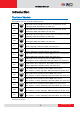
Hardware Manual Introduction The List of Models This hardware manual contains the following models: D71 D72 D81 D82 E71 E72 E73 E74 E81 E82 E83 E84 E85 E86 E87 1MP Outdoor Dome with D/N, IR, Fixed lens, f2.93mm/F2.0, H.264, 720p/30fps, DNR, MicroSDHC, PoE, IP66, IK10 3MP Outdoor Dome with D/N, IR, Fixed lens, f2.93mm/F2.0, H.264, 1080p/30fps, DNR, MicroSDHC, PoE, IP66, IK10 1MP Outdoor Dome with D/N, IR, Vari-focal lens, f2.8-12mm/F1.4, H.
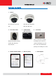
Hardware Manual Package Contents 1. Camera OR D71, D72, E71, E72, E73, D81, D82, E81, E82, E83, E74 E84, E85, E86, E87 2. Lens Focus Tuner 3. Conduit Gland 4. Screw Pack (Watertight Fitting) These screws are for surface Only provided with following mounting. If you need to use models: D71, D72, E71, specific mounting accessories, E72, E73,E74 the screws are included in the package of mounting accessories 5. Quick Installation Guide 6. Warranty Policy 5 7. Drill Template www.acti.
Hardware Manual Safety Instructions Cleaning Disconnect this video product from the power supply before cleaning. Attachments Do not use attachments not recommended by the video product manufacturer as they may cause hazards. Do not use accessories not recommended by the manufacturer Only install this device in a dry place protected from weather Servicing Do not attempt to service this video product yourself. Refer all servicing to qualified service personnel.
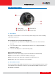
Hardware Manual Physical Description 1) Reset Button The purpose of reset button is to restore the factory default settings of the camera, including administrator’s password. The reset button can be used for following purposes: 1. The administrator’s password has been forgotten and therefore the camera cannot be accessed. 2. In case of IP address, mask, or allow/deny filter related issues, resulting with inability to modify these settings. 3. In case of connectivity issues or abnormal video quality.
Hardware Manual 3) Ethernet Port The IP device connects to the Ethernet via a standard RJ45 connector. 4) Conduit Hole Conduit holes are openings where cables pass through. There are two conduit holes on this device, used for different mounting angles. 8 www.acti.
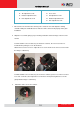
Hardware Manual Installation and Access Basic Connections 1) Remove the cover Remove the dome cover with Phillips screwdriver. 2) Insert the cable There are two conduit holes on the outdoor dome. One is at the bottom, while the other is at the side and covered with a plug. Remove the plug if your cable will go through the one at the side of the outdoor dome 3) Adjust viewing angle and focus The illustration shows where to adjust each axis.
Hardware Manual 1. Focus ring 1. Zoom lever 2. Tilt adjustment screw 2. Focus lever 3. Rotation adjustment axis 3. Tilt adjustment screw 4. Pan adjustment screw 4. Rotation adjustment axis 5. Pan adjustment screw 1. Based on the live view from the camera, please rotate the lens and adjust the viewing orientation with pan and tilt direction to make the dome camera work properly under given installation 2.
Hardware Manual Camera Installation There are several popular mounting types of installation methods for this IP outdoor dome camera. For more information about mounting solutions and accessories, please refer to the Buyer’s Guide. Mount Types Accessories Surface Mount Accessories not required Flush Mount PMAX-1003 L Type Wall Mount PMAX-0308 Pendant PMAX-0101+ PAMX-0103 Mount Gooseneck Pole Mount PMAX-0101+ PMAX-0303 + PMAX-0503 11 www.acti.
Hardware Manual Mount the IP Outdoor Dome (Surface) This camera can be surface mounted without needing any additional accessories. Use the screws from the screw pack and mount the camera to the surface using following screw holes. If you need to drill the holes to the surface first, such as concrete wall or ceiling, please use the drill template, provided in the camera package. 12 www.acti.
Hardware Manual Mount the IP Outdoor Dome (Flush) 13 www.acti.
Hardware Manual Mount the IP Indoor Dome (Wall) 14 www.acti.
Hardware Manual How to Do the Waterproof with Conduit Installation The following installation procedure makes the camera be water-resistant even for the situations where the camera can easily be flooded by pouring rain. The important part to focus on during the installation: The protection of the cabling has to be done by a proper flex conduit (corrugated tubing).
Hardware Manual 2. Pull the network cable through the flex conduit. Please note that the size of the conduit and the gland is big enough to let the RJ-45 connector pass through all the way, you may also consider to do the RJ-45 connector crimping after pushing the cable through the conduit. 3. Slide the clamping nut around flex conduit some 10-20 cm away from the top. Fit the sealing insert (made of rubber) to the top of the flex conduit. 4.
Hardware Manual 6. Connect the Ethernet cable to the camera’s network port. 7. Push the head of the flex conduit, wrapped with sealing insert, into the body of the conduit gland. 8. Screw the clamping nut tightly onto the body of the conduit gland. 9. Adjust the viewing angle and focus of the camera and put the dome cover back on, and tighten it by using the screws. 10. You have completed a fully waterproof installation, the camera is now ready to withstand even the most severe rain storms. 17 www.
Hardware Manual Accessing Camera Connect the Equipment To be able to connect to the camera firmware from your PC, both the camera and the PC have to be connected to each other via Ethernet cable. At the same time, the camera has to have its own power supply. In case of PoE cameras, you can use a PoE Injector or a PoE Switch between the camera and the PC. The cameras that have the DC power connectors may be powered on by using a power adaptor.
Hardware Manual In the example below, we successfully found D11 camera that we had just connected to the network. With the left mouse click on D11 it is possible to automatically launch the default browser of the PC with the IP address of the target camera filled in the address bar of the browser already. If you work with our cameras regularly, then there is even a better way to discover the cameras in the network – by using IP Utility.
Hardware Manual Use the default IP address of a camera: If there is no DHCP server in the given network, the user may have to assign the IP addresses to both PC and camera manually to make sure they are in the same network segment. When the camera is plugged into network and it does not detect any DHCP services, it will automatically assign itself a default IP: 192.168.0.100 Whereas the default port number would be 80.
Hardware Manual Manually adjust the IP addresses of multiple cameras: If there are more than 1 camera to be used in the same local area network and there is no DHCP server to assign unique IP addresses to each of them, all of the cameras would then have the initial IP address of 192.168.0.100, which is not a proper situation for network devices – all the IP addresses have to be different from each other.
Hardware Manual Access the Camera Now that the camera and the PC are both having their unique IP addresses and are under the same network segment, it is possible to use the Web browser of the PC to access the camera. You can use any of the browsers to access the camera, however, the full functionality is provided only for Microsoft Internet Explorer.
Hardware Manual Assuming that the camera’s IP address is 192.168.0.100, you can access it by opening the Web browser and typing the following address into Web browser’s address bar: http://192.168.0.100 Upon successful connection to the camera, the user interface called Web Configurator would appear together with the login page. The HTTP port number was not added behind the IP address since the default HTTP port of the camera is 80, which can be omitted from the address for convenience.