Bullet Camera Series Hardware Manual D41A, D42A, E42B, E43B, E47 Ver.
Hardware Manual Table of Contents Precautions 4 Safety Instructions ........................................................................... 6 Introduction 7 List of Models.................................................................................... 7 Package Contents............................................................................. 8 Physical Description ........................................................................ 9 Mounting Options ...................................
Hardware Manual Accessing the Camera 32 Configure the IP Addresses ........................................................... 32 Using DHCP Server to Assign IP Addresses ................................ 32 Using the Default Camera IP Address.......................................... 34 Access the Camera ......................................................................... 36 3 www.acti.
Hardware Manual Precautions Read these instructions You should read all the safety and operating instructions before using this product. Heed all warnings You must adhere to all the warnings on the product and in the instruction manual. Failure to follow the safety instruction given may directly endanger people, cause damage to the system or to other equipment.
Hardware Manual Federal Communications Commission Statement This equipment has been tested and found to comply with the limits for a class B digital device, pursuant to Part 15 of the FCC Rules. These limits are designed to provide reasonable protection against harmful interference in a residential installation. This equipment generates, uses, and can radiate radio frequency energy and, if not installed and used in accordance with the instructions, may cause harmful interference to radio communications.
Hardware Manual Safety Instructions Don’t open the housing of the product Cleaning Disconnect this video product from the power supply before cleaning. Attachments Do not use attachments not recommended by the video product manufacturer as they may cause hazards. Water and Moisture Do not use this video product near water, for example, near a bathtub, washbowl, kitchen sink, or laundry tub, in a wet basement, or near a swimming pool and the like.
Hardware Manual Introduction List of Models This hardware manual contains the following models: D41A 1MP Bullet with D/N, Adaptive IR, Vari-focal lens D42A 3MP Bullet with D/N, Adaptive IR, Vari-focal lens E42B 3MP Bullet with D/N, Adaptive IR, Basic WDR, Vari-focal lens E43B 5MP Bullet with D/N, Adaptive IR, Basic WDR, Vari-focal lens E47 1.3MP Bullet with D/N, Adaptive IR, Basic WDR, SLLS, Vari-focal lens 7 www.acti.
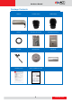
Hardware Manual Package Contents Camera Conduit Gland Cable Gland Washer Mounting Screw Kit Sunshield Screw Kit Bracket Bracket Plate Sunshield Warranty Card Quick Installation Guide 8 www.acti.
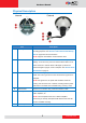
Hardware Manual Physical Description Item 1 Memory Card Slot Description Insert a memory card (not included) into this slot for local recording purposes. See How to Install / Remove the Memory Card on page 28 for more information. NOTE: Supports microSDHC and microSDXC cards. 2 Reset Button Use the Reset Button to reset the camera to its factory default settings. To do the reset, press and hold the Reset button for at least 5 seconds or until the Power LED lights up.
Hardware Manual Item 7 Digital Input / Output Description Connects to digital input or output devices, such as an alarm trigger, panic button, etc. Digital Input (DI) and Digital Output (DO) devices are used in applications like motion detection, event triggering, alarm notifications, etc. See How to Connect DI/DO Devices (Optional) on page 24 for information on how to connect DI/DO devices to your camera. 10 www.acti.
Hardware Manual Mounting Options In areas with fierce weather conditions, the light bundled bracket can be replaced by a heavy duty outdoor bracket combined with additional mounting accessories. Below are the optional mounting accessories that you can use with the camera. Mount Types Accessories Corner Mount Suitable when mounting the camera on a corner wall. PMAX-1103 PMAX-0402 + Pole Mount Suitable when mounting the camera on a pole.
Hardware Manual Installation Procedures Using the Bundled Bracket Step 1: Install the Bundled Bracket 1. Mark the location of the three (3) screw holes using the bracket plate included in the package. NOTE: Depending on the surface where you will install the camera, it may be necessary to drill the holes and use the supplied screw tox. 2. Attach the plate to the surface using the three (3) supplied screws. 3. Attach the bracket to the plate. 12 www.acti.
Hardware Manual Step 2: Attach the Sunshield The use of sunshield is optional if the camera will be installed indoors. However, if the camera will be installed outdoors, attach the sunshield to protect the lens from all types of weather and lighting conditions. 1. Loosely secure the supplied screws and washers to attach the sunshield. 2. Slide to adjust the sunshield to cover the lens as far as possible but out of the camera’s live view. 3. Tighten the screws to fix the position of the sunshield.
Hardware Manual Step 3: Install the Camera 1. If necessary, install a memory card to the camera. See How to Insert the Memory Card on page 28 for more information. 2. Depending on how you want to install the camera, attach the camera to the bracket through one of the two (2) holes below: 3. Adjust the camera viewing angle and tighten the knob to fix the camera position. 14 www.acti.
Hardware Manual Step 4: Waterproof and Connect the Cable The camera and the pre-installed network cable, “pigtail”, are resistant to salt, water, weak acid, alcohol, oil, grease and other common solvents. However, users must ensure that the cable connection and the network side cable itself are also protected from different environmental factors. For Ethernet connection, there are two waterproofing methods.
Hardware Manual How to Use the Cable Gland This section describes how to waterproof the cable-out or “pigtail” of the camera using the bundled cable gland. An exterior-grade Ethernet cable is required. The camera may or may not have to be installed first before doing the cable connections (see related installation procedures for details).
Hardware Manual 2. Insert the clamping nut into the Ethernet cable. 3. Insert the sealing insert with claw. 4. Insert the gland body into the Ethernet cable. 5. On the “pigtail” side, insert the washer into the “pigtail”. 17 www.acti.
Hardware Manual 6. Connect the Ethernet cable connector to the “pigtail” connector. 7. Attach the gland body to the “pigtail”. NOTE: Make sure the gland body is tightly attached to the “pigtail” and the washer is secured between them. 8. Insert the sealing insert into the cable gland body and then attach the clamping nut to complete the cable solution. NOTE: Make sure the clamping nut is tightly attached to the cable gland body and the sealing insert is squeezed tightly. 18 www.acti.
Hardware Manual How to Use the Conduit Gland This section describes how to waterproof the cable-out or “pigtail” of the camera using the bundled conduit gland and flexible conduit. This is the recommended solution if an exterior-grade Ethernet cable is not available. Before connection, prepare the following materials: Flexible Conduit 1/2" Trade size (not included in the package) Conduit Gland (included in the camera package) NOTE: Not included in the package.
Hardware Manual 2. Pull the Ethernet cable through the flex conduit. Leave enough length of the cable outside the flex conduit. 3. Insert the clamping nut through the flex conduit. 4. Insert the sealing nut and fix it at the end of the flex conduit. 5. Insert the gland body into the Ethernet cable. 20 www.acti.
Hardware Manual 6. On the “pigtail” side, insert the washer into the “pigtail”. 7. Connect the Ethernet cable connector to the “pigtail” connector. 8. Attach the gland body to the “pigtail”. NOTE: Make sure the gland body is tightly attached to the “pigtail” and the washer is secured between them. 21 www.acti.
Hardware Manual 9. Push the flex conduit and insert the sealing nut into the gland body. NOTE: Make sure the clamping nut is tightly attached to the cable gland body and the sealing insert is squeezed tightly. 10. Attach the clamping nut to complete the cable solution. 22 www.acti.
Hardware Manual Step 5: Connect the Cable Connect the other end of the network cable to a switch or injector. Then, connect the switch or injector to a network, PC, and a power source. See Power-over-Ethernet (PoE) connection example below. Network Ethernet Cable Ethernet Cable (Data) PoE Injector Power Cable Ethernet Cable (Data + Power) AC Power Source Camera Step 6: Access the Camera Live View See Accessing the Camera on page 32 for more information on how to access the Live View of the camera.
Hardware Manual Other Connections This section describes the procedures in connecting Digital Input and Output (DI/DO) and Audio Input and Output devices. The use of these devices, however, is optional. Audio Input/Output Jacks DI/DO Wires NOTE: If these connectors will not be used, leave the rubber caps on and the wires twisted together to ensure cables remain waterproof and eliminate short-circuit hazards.
Hardware Manual Understanding the DI/DO Cables You can connect up to one (1) DI and one (1) DO device to your camera.
Hardware Manual Typical Connection Based on these specifications, if the DI device has a voltage of 0V ~ 30V or the DO device has a voltage of < 24V (< 50mA), then the camera can supply internal power to these devices and there is no need to connect the DI/DO device to an external power source. In this case, wire connection to Pins 1 to 4. Use the DIO GND and DI pins to connect a DI device and use the DIO PW and DO pins to connect a DO device.
Hardware Manual The illustration below is a graphic example of connecting a relay to a high voltage DO device. 110V-220V AC External Power Source Relay (DO1 Device) ) Camera Illuminator NOTE: For more information on DI/DO connections, please refer to the Knowledge Base article All about Digital Input and Digital Output downloadable from the link below (http://www.acti.com/kb/detail.asp?KB_ID=KB20091230001).
Hardware Manual Adjustments and Accessories This section describes the procedures on installing a memory card and resetting the camera. How to Install / Remove the Memory Card The camera supports local video recording or saving of snapshots to a memory card. NOTE: Supports microSDHC and microSDXC cards. How to Insert the Memory Card 1. Loosen the three (3) screws to detach the back cover. NOTE: A cable is connected inside the camera; do not abruptly pull the back cover. 2.
Hardware Manual 3. When done, ensure the rubber seal is aligned and attached to the back cover and then close the back cover by tightening the three (3) screws. CAUTION: Make sure the rubber seal is properly attached and the back cover is closed to ensure water or dust cannot enter the camera. How to Remove the Memory Card In case there is a need to remove the card, make sure to access the camera Web Configurator to safely “unmount” the card first (see the camera Firmware manual for more information).
Hardware Manual Adjust the Viewing Angle and Focus The camera already comes pre-focused when taken out of the box. If there is a need to change the viewing angle and focus, follow the steps below to adjust them. 1. Open the front cover. 2. Loosen the lever screws. Based on the live view, move the levers to adjust the focus and viewing angle of the target area . Focus Lever Screw Viewing Angle Lever Screw 3. When done, tighten back the lever screws to fix their position. 4. Close the front cover.
Hardware Manual How to Reset the Camera In case there is a need to reset the camera to its default factory settings, do the following procedures while the camera is powered on. 1. Loosen the three (3) screws securing the back cover. NOTE: A cable is connected inside the camera; do not abruptly pull the back cover. 2. Using a pointed object, such as the tip of a pen, press and hold the Reset button for at least 5 seconds or until the Power LED lights up, to reset the camera. 3.
Hardware Manual Accessing the Camera Configure the IP Addresses In order to be able to communicate with the camera from your PC, both the camera and the PC have to be within the same network segment. In most cases, it means that they both should have very similar IP addresses, where only the last number of the IP address is different from each other. There are 2 different approaches to IP Address management in Local Area Networks – by DHCP Server or Manually.
Hardware Manual If you work with our cameras regularly, then there is even a better way to discover the cameras in the network – by using IP Utility. The IP Utility is a light software tool that can not only discover the cameras, but also list lots of valuable information, such as IP and MAC addresses, serial numbers, firmware versions, etc, and allows quick configuration of multiple devices at the same time. The IP Utility can be downloaded for free from http://www.acti.
Hardware Manual Using the Default Camera IP Address If there is no DHCP server in the given network, the user may have to assign the IP addresses to both PC and camera manually to make sure they are in the same network segment. When the camera is plugged into network and it does not detect any DHCP services, it will automatically assign itself a default IP: 192.168.0.100 Whereas the default port number would be 80.
Hardware Manual Manually adjust the IP addresses of multiple cameras: If there are more than one camera to be used in the same local area network and there is no DHCP server to assign unique IP addresses to each of them, all of the cameras would then have the initial IP address of 192.168.0.100, which is not a proper situation for network devices – all the IP addresses have to be different from each other.
Hardware Manual Access the Camera Now that the camera and the PC are both having their unique IP addresses and are under the same network segment, it is possible to use the Web browser of the PC to access the camera. You can use any of the browsers to access the camera, however, the full functionality is provided only for Microsoft Internet Explorer.
Hardware Manual The following examples in this manual are based on Internet Explorer browser in order to cover all functions of the camera. Assuming that the camera’s IP address is 192.168.0.100, you can access it by opening the Web browser and typing the following address into Web browser’s address bar: http://192.168.0.100 Upon successful connection to the camera, the user interface called Web Configurator would appear together with the login page.
Copyright © 2014, ACTi Corporation All Rights Reserved 7F, No. 1, Alley 20, Lane 407, Sec. 2, Ti-Ding Blvd., Neihu District, Taipei, Taiwan 114, R.O.C. TEL : +886-2-2656-2588 FAX : +886-2-2656-2599 Email: sales@acti.