Indoor Dome Series Hardware Manual D61, D62, D64, D65, E61, E62, E63, E64, E65, E66, E67 2014/05/07
Hardware Manual Table of Contents Precautions ............................................................. 4 Safety Instructions .................................................................................... 6 Introduction ............................................................. 7 The List of Models ..................................................................................... 7 Package Contents......................................................................................
Hardware Manual How to Remove the Memory Card ........................................................ 26 Accessing the Camera ......................................... 27 Configure the IP Addresses .................................................................... 27 Access the Camera.................................................................................. 31 3 www.acti.
Hardware Manual Precautions Read these instructions You should read all the safety and operating instructions before using this product. Heed all warnings You must adhere to all the warnings on the product and in the instruction manual. Failure to follow the safety instruction given may directly endanger people, cause damage to the system or to other equipment.
Hardware Manual Federal Communications Commission Statement This equipment has been tested and found to comply with the limits for a class B digital device, pursuant to Part 15 of the FCC Rules. These limits are designed to provide reasonable protection against harmful interference in a residential installation. This equipment generates, uses, and can radiate radio frequency energy and, if not installed and used in accordance with the instructions, may cause harmful interference to radio communications.
Hardware Manual Safety Instructions Cleaning Disconnect this video product from the power supply before cleaning. Attachments Do not use attachments not recommended by the video product manufacturer as they may cause hazards. Do not use accessories not recommended by the manufacturer Only install this device in a dry place protected from weather Servicing Do not attempt to service this video product yourself. Refer all servicing to qualified service personnel.
Hardware Manual Introduction The List of Models This hardware manual contains the following models: D61 1.
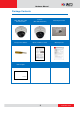
Hardware Manual Package Contents Camera (D64, D65, E61, E62, E63, E64, E65) Camera (D61, D62, E66, E67) Mounting Screw Kit Hexagon Screwdriver Quick Installation Guide Warranty Card Drill Template Drill Template 8 www.acti.
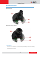
Hardware Manual Physical Description D61, D62, E66, E67 D64, D65, E61, E62, E63, E64, E65 1) Reset Button The purpose of reset button is to restore the factory default settings of the camera, including the administrator’s password. 9 www.acti.
Hardware Manual The reset button can be used for following purposes: The administrator’s password has been forgotten and therefore the camera cannot be accessed. 1. In case of IP address, mask, or allow/deny filter related issues, resulting with inability to modify these settings. 2. In case of connectivity issues or abnormal video quality. How to do the reset properly? Using a pointed object, such as a paper clip, press and hold the reset button for 5 seconds.
Hardware Manual Mounting Options There are several mounting options that you can use to install the camera. Select the most suitable solution for your installation environment. Mount Types Accessories Surface Mount Suitable when mounting the camera directly on walls or ceilings Flush Mount Suitable when mounting the camera discretely above dropped ceilings wherein only the dome cover will be visible underneath without extra accessories.
Hardware Manual Mount Types Accessories Straight Wall Mount Suitable when mounting the camera on straight walls. PMAX-0308 (L-Type Wall Mount) PMAX-0101 PMAX-0305 (Heavy Duty Wall Mount) Vertical Pole Mount Suitable when mounting the camera on vertical poles. Horizontal Pole Mount Suitable when mounting the camera on horizontal poles. PMAX-0101 PMAX-0101 Corner Mount PMAX-0305 PMAX-0102 PMAX-0503 PMAX-0503 Suitable when mounting the camera on a corner wall.
Hardware Manual Other Mounting Accessories Accessories PMAX-0104 (Extension Tube) NOTE: For more information about the mounting solutions and accessories, please check the Mounting Accessory Selector in our website (http://www.acti.com/mountingselector). The above mounting accessories are not included in the package. Contact your sales agents to purchase. 13 www.acti.
Hardware Manual Installing the Camera on a Surface This section describes the procedures in installing the camera on a flat surface such as a hard or dropped ceiling and straight or tilted walls. Before installation, make sure the wall or the ceiling can bear more than the weight of the camera. Step 1: Drill the Holes Before drilling the holes on the ceiling or wall, note the direction of the connectors side of the camera, which is also the opposite side of the camera logo.
Hardware Manual Step 2: Open the Dome Cover NOTE: To avoid scratches or leaving fingerprints on the dome cover, it is recommended to retain the plastic covering the dome cover until the camera is completely installed. 1. With the bundled hex screwdriver, loosen the three (3) screws securing the dome cover. 2. Lift to remove the dome cover. 3. For D61, D62, E66, E67 models, remove the styrofoam from the camera lens. 15 www.acti.
Hardware Manual 4. If the cables will be routed along the ceiling or wall, remove the cable tab from the dome cover. 5. If the cables will pass through the ceiling or wall, route and pull the cables through the hole on the surface. Step 3: Install the Camera to the Surface 1. If necessary, insert a memory card, with the metallic contacts facing down, into the card slot of the camera. 2.
Hardware Manual CAUTION: When using electric screwdrivers, be careful not to touch the camera components while attaching the screws. Since electric screwdrivers vary in sizes, speed, and force, they may bruise and damage the camera components. DISCLAIMER: ACTi will not be responsible for camera damage caused by improper installations or the misuse of equipment for installation. Step 4: Connect the Cable 1. Connect the network cable to the Ethernet port of the camera. Ethernet Port 2.
Hardware Manual Step 5: Access the Camera Live View See Accessing the Camera on page 27 for more information on how to access the Live View of the camera. Step 6: Adjust the Viewing Angle and Focus Based on the camera live view, adjust the viewing angle, orientation and focus of the camera. Adjustments vary depending on model, see How to Adjust the Camera Viewing Angle and Focus on page 20 for more information. Step 7: Close the Dome Cover 1.
Hardware Manual 3. Tighten the three (3) screws to attach the dome cover to the camera body. 4. Remove the plastic covering the dome cover. Final installation should look similar to the illustration below. 19 www.acti.
Hardware Manual Other Adjustments and Accessories How to Adjust the Camera Viewing Angle and Focus This section describes procedures in adjusting the viewing angle, focus, and pan direction of the camera. D61, D62, E66, E67 Camera Models Camera Parts Overview Adjustment Procedures 3 2 4 1 20 www.acti.
Hardware Manual 1. Loosen the tilt adjustment screws, adjust the tilt, and then tighten back the screws to fix the tilt position. 2. Turn the rotation adjustment to rotate the viewing orientation. 3. Loosen the pan adjustment screw, move the pan direction, and then tighten back the screw to fix the pan position. 4. Move the zoom and focus levers left or right to adjust the focus and the viewing angle. 21 www.acti.
Hardware Manual D64, D65, E61, E62, E63, E64, E65 Camera Models Camera Parts Overview Adjustment Procedures 3 2 4 1 1. Loosen the tilt adjustment screws, adjust the tilt, and then tighten back the screws to fix the tilt position. 2. Turn the rotation adjustment to rotate the viewing orientation. 3. Loosen the pan adjustment screw, move the pan direction, and then tighten back the screw to fix the pan position. 4. Move the zoom and focus levers left or right to adjust the focus and the viewing angle.
Hardware Manual How to Replace the Dome Cover For more discrete surveillance needs, the bundled dome cover can be replaced with a smoke, vandal proof cover available for purchase. To replace the dome cover, do the following: 1. Loosen the three (3) screws to open the dome cover. 2. Remove the three (3) screws to detach the bracket. 3. Remove the bracket and dome cover from the cover housing. 23 www.acti.
Hardware Manual 4. Remove the shroud from the dome cover. 5. Place the shroud on the replacement dome cover. 6. Insert the replacement dome cover into the cover housing. 7. Align and attach the three (3) screws to secure the bracket to the cover housing. 24 www.acti.
Hardware Manual 8. Attach the dome cover to the camera by tightening the three (3) screws. Final installation should look similar to the illustration below. 25 www.acti.
Hardware Manual How to Use a Memory Card The camera supports local video recording or saving of snapshots to a memory card. NOTE: Supports microSDHC and microSDXC cards. How to Insert the Memory Card Insert a memory card into the card slot with the metallic contacts facing down the camera. Push the card until it clicks into place.
Hardware Manual Accessing the Camera Configure the IP Addresses In order to be able to communicate with the camera from your PC, both the camera and the PC have to be within the same network segment. In most cases, it means that they both should have very similar IP addresses, where only the last number of the IP address is different from each other. There are 2 different approaches to IP Address management in Local Area Networks – by DHCP Server or Manually.
Hardware Manual Double-click on the camera model name, the default browser of the PC is automatically launched and the IP address of the target camera is already filled in the address bar of the browser. If you work with our cameras regularly, then there is even a better way to discover the cameras in the network – by using IP Utility.
Hardware Manual Use the default IP address of a camera: If there is no DHCP server in the given network, the user may have to assign the IP addresses to both PC and camera manually to make sure they are in the same network segment. When the camera is plugged into network and it does not detect any DHCP services, it will automatically assign itself a default IP: 192.168.0.100 Whereas the default port number would be 80.
Hardware Manual Manually adjust the IP addresses of multiple cameras: If there are more than 1 camera to be used in the same local area network and there is no DHCP server to assign unique IP addresses to each of them, all of the cameras would then have the initial IP address of 192.168.0.100, which is not a proper situation for network devices – all the IP addresses have to be different from each other.
Hardware Manual Access the Camera Now that the camera and the PC are both having their unique IP addresses and are under the same network segment, it is possible to use the Web browser of the PC to access the camera. You can use any of the browsers to access the camera, however, the full functionality is provided only for Microsoft Internet Explorer.
Hardware Manual The following examples in this manual are based on Internet Explorer browser in order to cover all functions of the camera. Assuming that the camera’s IP address is 192.168.0.100, you can access it by opening the Web browser and typing the following address into Web browser’s address bar: http://192.168.0.100 Upon successful connection to the camera, the user interface called Web Configurator would appear together with the login page.
Hardware Manual To check the firmware version through the Web Configurator, access the Setup page and click System > System Info. 1 2 3 For further operations, please refer to the Firmware User Manual. 33 www.acti.