
User manual

www.acti.com
ECD-1000 User Manual
15
1.2 Connecting Devices
Connection Architecture
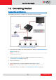
The diagram below illustrates a sample connection within a local area network.
Local Area Network Connection Architecture
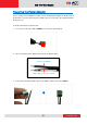
1. Connect the power adaptor to the Decoder and power outlet (see Preparing the Power
Adaptor on page 16).
NOTE: This step may be skipped if a Power-over-Ethernet (PoE) switch or injector will be
connected to the Decoder.
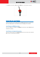
2. Connect a monitor to the Decoder via HDMI or Composite port connection (see
Connecting to Local Display on page 17).
3. Connect a USB mouse.
4. Connect the Decoder to a Power-over-Ethernet (PoE) switch or injector.
NOTE: If using the bundled power adaptor, a non-PoE switch may also be used.
5. Connect the cameras to the switch (see Connecting the Cameras on page 18).