KCM-7311 3.6x Zoom H.264 4-Megapixel IP D/N Vandal Proof PoE Rugged Dome with PIris, Advanced WDR (DC 12V / PoE) Ver.
KCM-7311 Hardware User’s Manual Table of Contents 0. Precautions 3 1. Introduction 4 Package Contents ........................................................................... 4 Features and Benefits ..................................................................... 5 Safety Instructions .......................................................................... 7 Physical description ........................................................................ 9 Product Specification ................
KCM-7311 Hardware User’s Manual 0. Precautions Read these instructions You should read all the safety and operating instructions before using this product. Heed all warnings You must adhere to all the warnings on the product and in the instruction manual. Failure to follow the safety instruction given may directly endanger people, cause damage to the system or to other equipment.
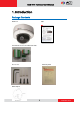
KCM-7311 Hardware User’s Manual 1. Introduction Package Contents KCM-7311 QIG Terminal Blocks for Power DI/O and Audio Accessories Warranty Card Drill Template 4 www.acti.
KCM-7311 Hardware User’s Manual Features and Benefits This is a cutting edge network video surveillance camera. It can capture, compress and transmit real time video in excellent quality (8 FPS 4Megapixel, 2032 x 1920). This camera is your best choice to build an intelligent IP surveillance system. Adaptive Profile With the innovative embedded Image Signal Processor (ISP), this camera responds to changing lighting condition with customized algorithm.
KCM-7311 Hardware User’s Manual Powerful Bundled Surveillance Software To extend the capabilities of the IP Dome Camera series, a powerful surveillance program is included in the package for free. Users can easily use an existing PC as a digital video recorder. Scheduled recording and manual recording keep every important video recorded in the local hard disk. Reliable and accurate motion detection with instant warning enables immediate response in every condition.
KCM-7311 Hardware User’s Manual Safety Instructions Don’t use the power supply with other voltages This device is likely to be damaged or damage other equipments / personnel, if you use a power supply with different voltage than the one included with this device. All warranty of this product will be voided in the situations above. Don’t open the housing of the product Cleaning Disconnect this video product from the power supply before cleaning.
KCM-7311 Hardware User’s Manual this manual. Adjust only those controls that are covered by the instruction manual, as an improper adjustment of other controls may result in damage, and will often require extensive work by a qualified technician to restore the video product to its normal operation. Safety Check Upon completion of any service or repairs to this video product, ask the service technician to perform safety checks to determine if the video product is in proper operating condition. 8 www.
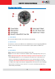
KCM-7311 Hardware User’s Manual Physical description 1) Power Button Press the Power Button and then camera will reboot automatically. 2) Ethernet Port The IP device connects to the Ethernet via a standard RJ45 connector. Supporting NWAY, this IP device can auto detect the speed of local network segment (10Base-T/100Base-TX Ethernet). 3) Reset Button Step 1: Switch off IP device by disconnecting the power cable Step 2: Press and continue to hold the Reset Button (with a sharp tipped object, like a pen.
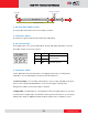
KCM-7311 Hardware User’s Manual Restore to Default Complete Power On On (3s) On 1s Off (about 15s) Off (10~15s) Stay On About 20 Seconds 4) Micro SD / Micro SDHC Card Slot* Insert your Micro SD card here for local recording on camera 5) Audio Input / Output The IP device supports audio input and output via terminal block 6) DC 12V Power Input Connect DC power source to the terminal block. The wire with white dashed lines is the live wire, which should connect to the 12V pin.
KCM-7311 Hardware User’s Manual Pin 1 GND Ground. Connect with Pin 3 for DI control loop. Pin 2 12V Provides power to external devices with a Voltage: 12V DC, maximum current of 100mA. Max: 1.2W Connect to GND to activate, or leave floating Must not be exposed (or unconnected) to deactivate. to voltages greater Pin 3 Digital Input than 30V DC. Pin 4 Transistor Connect to Pin 2 through external devices for Max load = <100mA Output DO loop.
KCM-7311 Hardware User’s Manual Product Specification KCM-7311 • Device Device Type Image Sensor Sensor Size Horizontal Resolution Day / Night Minimum Illumination Color to B/W switch Mechanical IR Cut Filter IR Sensitivity Range IR LED Electronic Shutter • Lens Focal Length Zoom Ratio Iris Focus Mount Type Horizontal Viewing Angle Viewing Angle Adjustment Fixed Dome Camera Aptina Progessive Scan CMOS 1/3.2” (4.5 x 3.4 mm) 1422 TVL Yes Color: 0.1 lux at F1.4 (30 IRE, 2400°K); B/W: 0.05 lux at F1.
KCM-7311 Hardware User’s Manual • Alarm Alarm Trigger Alarm Response • Interface Digital Input Digital Output Local Storage • General Power Source / Consumption Weight Dimensions (Φ x H) Environmental Casing Mount Type Operating Temperature Operating Humidity Approvals • Integration Unified Solution ISV Integration Firmware Access Browser Video motion detection 3 regions in single view mode, 1 region each in 4 cropped VGA mode; External device through digital input Notify control center; Go to Zoom prese
KCM-7311 Hardware User’s Manual 2. Installation Procedure Connecting the IP Outdoor Rugged Dome 1) Remove the cover Remove the dome cover with special hex wrench in the accessory kit. zz 2) Insert the cable There are two conduit holes on this rugged dome. One is at the bottom, while the other is at the side and covered with a plug.
KCM-7311 Hardware User’s Manual How to Do the Waterproof Installation The following installation procedure makes the camera be water-resistant even for the situations where the camera can easily be flooded by pouring rain. The important part to focus on during the installation: The protection of the cabling has to be done by a proper flex conduit. The size of the flex conduit that matches with the conduit gland is is 3/4” (trade size), or with actual physical diameter of 26.441mm.
KCM-7311 Hardware User’s Manual Scenario 1 – using the side hole. Scenario 2 – using the bottom hole. Screw the body of the conduit gland into the camera and fix it with the lock nut (included in the set of conduit gland that you purchased) from the inside of the camera.. Connect the Ethernet cable to the camera’s network port. If you are not using PoE, then please remember to pull the DC power cable through the flex conduit as well, and connect to the camera at this point. 16 www.acti.
KCM-7311 Hardware User’s Manual Push the head of the flex conduit, wrapped with sealing insert, into the body of the conduit gland. Screw the clamping nut tightly onto the body of the conduit gland. Adjust the viewing angle and focus of the camera and put the dome cover back on, and tighten it by using the screws. You have completed a fully waterproof installation! 17 www.acti.
KCM-7311 Hardware User’s Manual 3. Accessing Camera If you have DHCP server / router in your network: Many network server / routers are able to automatically provide IP addresses through DHCP. If you are using such a network, just plug in your computer and IP Dome Cam into the network and your IP device will acquire network address by itself. Find and access the device with our IP Utility program. You may download it at: http://www.acti.
KCM-7311 Hardware User’s Manual 4. Open Internet Explorer (Version 6.0 or above) , and type in the Default IP: 192.168.0.100 5. When you see the login window, please input default user and password: Default User: Admin Password: 123456 6. After logging in, you will see the video from camera. To go to the main menu, click the ”Setup” button on the top left. 19 www.acti.
KCM-7311 Hardware User’s Manual If you are using a single camera, this is enough to access the device. If you are using multiple devices, you need to change the current device to another unused IP address, so that when the next device is connected to the network, no two devices use the same IP. Please perform the following steps. 7. Go to Network -> Connection Type 8. Change the IP mode to Static. 9. Change the IP to 192.168.0.101 or any other unused IPs. Do NOT use the PC’s IP address or 192.168.0.