
User Manual

www.acti.com
KCM-7311 Hardware User’s Manual
10
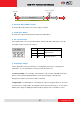
On (3s)
On
1s
Power On
About 20 Seconds
Stay On
Off (about 15s)
Off (10~15s)
Restore to Default
Complete
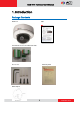
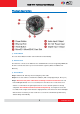
4) Micro SD / Micro SDHC Card Slot*
Insert your Micro SD card here for local recording on camera
5) Audio Input / Output
The IP device supports audio input and output via terminal block
6) DC 12V Power Input
Connect DC power source to the terminal block. The wire with white dashed lines is the live
wire, which should connect to the 12V pin.
7) Digital Input / Output
Used in applications like motion detection, event triggering, time lapse recording, alarm
notifications, etc., the I/O terminal connector provides the interface to:
•2 transistor output - For connecting external devices such as relays and LEDs. Connected
devices can be activated by Output buttons on the Live View page or through video
management software. Connect Pin 2 with 4 or 6 with 8.
•2 Digital Input - An alarm input for connecting devices that can toggle between an open and
closed circuit, for example: PIRs, door/window contacts, glass break detectors, etc. The device
will detect the change in digital input and transmit the signal to video surveillance servers.
PIN
NAME
DESCRIPTION
1
N
AC Power Input
2
L
3
GND
E-Ground of power