HR7012M / HR7012S Custom Vehicle Headrests with 7” Slim Style LED LCD Satellite Monitors or Built-in DVD Player for Rear Entertainment S HR7012M S P HR7012S Installation Guide 128-9047
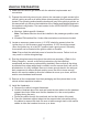
IMPORTANT NOTICE Installation of headrest products require careful planning and preparation. Be extremely careful of seats that have airbags built into them. Keep wiring away from any air bag wiring (usually identified by yellow connectors and yellow wire jackets). Damage to air bag wiring can result in personal injury to vehicle occupants. If you have any questions regarding wire routing or installation in a vehicle, please contact Audiovox Technical Support at 1-800-225-6074.
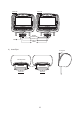
MATERIAL TO USE IN THIS PACKAGE: 1) HR7012 System Monitor (P/N HR7012M/HR7012S) (2 pcs) Custom Vehicle Headrests with 7” Slim Style LED LCD Satellite Monitors or Built-in DVD Player for Rear Entertainment Note: The HR7012M/HR7012S monitor has been designed to be interchangeable from one headrest to the other.
2) HR7012GP Game Module Package (P/N HR7012GP) (1 pc) OPTIONAL The Game Module Package contains the following items: a) Game Controller P1 (P/N 136-5239) - (1pc) RESET c) Game Module (P/N 136-5238) - (1pc) SELECT Y B START X A P1 b) Game Controller P2 (P/N 136-5240) - (1pc) RESET d) Game Module Manual (P/N 128-9048) - (1pc) SELECT Y B START X A P2 Note: The HR7012GP Game Package is the optional accessories package. For user to upgrade with the wireless game source feature.
HR7012 SYSTEM OVERVIEW 1) The HR7012 is a versatile audio / video system with built-in DVD (HR7012M only) which includes two monitors, that can accept an Audio / Video input and independent AUX input. A separate audio output is provided for connecting the FM Modulator to the vehicle's radio.
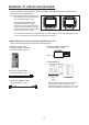
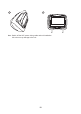
HR7012M HR7012S S P S PULL UP VIDEO PULL UP AUDIO L AUDIO R USB WIRED HEADPHONE AUDIO R VIDEO AUDIO L AUDIO R AUDIO L VIDEO 9) Insert/Eject 20 degrees Insert/Eject Disc Inner Ring HR7012M HR7012S 6
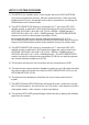
VEHICLE PREPARATION 1) Read the manuals and get familiar with the electrical requirements and connections. 2) Prepare the vehicle by removing any interior trim necessary to gain access to the vehicle's wiring as well as all areas where interconnecting wire harnesses will be located. The mounting method and the location will vary from vehicle to vehicle, so this manual will only focus on the installation of the Master and Satellite Monitors in the supplied configuration.
7) Connect all the components together (electrically) and verify proper operation of all the system functions. a. The headrest DIN cables and the FMM Interface Box DIN cables are color coded. Connect each headrest cable to the correct color cable on the FMM Interface Box. b. Extend the wireless FM antenna to its full length and orientate for best reception. Do not place it on the FMM Interface Box or near metal. c. Connect the DC power jack.
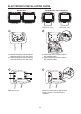
ELECTRONICS INSTALLATION GUIDE Monitor Unit Install Monitor Unit to Headrest S S S (HR7012M) S P (HR7012S) (HR7012M/ HR7012S - M1) (HR7012M/ HR7012S - M2) 2 1 a b a b a.) Match MH1/SH1 monitor cable to M1 headrest cable b.) Match MH2/SH2 monitor cable to M2 headrest cable a.) Master/Satellite monitor headrest cable (MH1/SH1) 8Pin Din Cable. b.) Master/Satellite monitor headrest cable (MH2/SH2) 9Pin Din Cable.
6 5 Note: Switch off the ACC power during cable and unit installation. fail to do so may damage to the unit.
HR7012 SYSTEM WIRING DIAGRAM HR7012M / HR7012S HR7012M / HR7012S Master Monitor Satellite Monitor S 112-4208 S 112-4209 P 112-4210 112-4211 12 Pin AV Adapter Cable GREEN RED BLUE DC IN 2 PIN DC POWER CABLE AV Input AV Output INTERFACE BOX FM ANTENNA OPTIONAL OPTIONAL OF HR7012GP (GAME PACKAGE) Relay Box SIRSWB HR7012GP Relay Box for wireless FM MOD See antenna note below See the instructions supplied with the SIRSWB for installation.
© 2012 Audiovox Electronics Corp.