User’s Manual 9640 Professional Enhanced Scan Tool
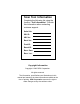
Scan Tool Information Complete the following list using the function “Tool Information”. Provide this information when contacting customer support. Serial No: SW ID: HW Ver: Boot Ver: Prod ID: Board ID: Burn Date: Burn Loc: Copyright Information Copyright © 2005 SPX Corporation. All rights reserved. The information, specifications and illustrations in this manual are based on the latest information available at the time of printing.
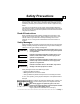
Safety Precautions For your safety, read this manual thoroughly before operating your Professional Enhanced Scan Tool. Always refer to and follow safety messages and test procedures provided by the manufacturer of the vehicle or equipment being tested. Your scan tool is intended for use by properly trained, skilled professional automotive technicians. The safety messages presented below and throughout this user’s manual are reminders to the operator to exercise extreme care when using this test instrument.
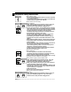
Safety Precautions ! Important Safety Instructions Risk of electric shock. • Do not exceed voltage limits between inputs as indicated in the “Specifications”. • Use extreme caution when working with circuits that have greater than 60 volts DC or 24 volts AC. Electric shock can cause injury. ! WARNING ! WARNING ! WARNING Risk of explosion. • Wear safety goggles and protective clothing, user and bystander. Everyday eyeglasses only have impact resistant lenses, they are NOT safety glasses.
Safety Precautions • Do not position head directly over or in front of throttle body. Do not pour gasoline down throttle body when cranking or running engine, when working with fuel delivery systems or any open fuel line. Engine backfire can occur when air cleaner is out of position. • Do not use fuel injector cleaning solvents when performing diagnostic testing. • Keep cigarettes, sparks, open flame and other sources of ignition away from vehicle.
Safety Precautions Risk of injury. • This equipment should be operated by qualified personnel only. • Use this equipment only as described in this manual. Use only the manufacturer’s recommended attachments. • Do not operate equipment with a damaged cord or if the equipment has been dropped or damaged, until it has been examined by a qualified service representative. Operation of this equipment by anyone other than qualified personnel may result in injury.
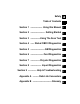
Safety Table of Contents ToC ! Section 1 –––––––––– Using this Manual 1 Section 2 –––––––––––– Getting Started 2 Section 3 ––––––––Using The Scan Tool 3 Section 4 ––– Global OBD II Diagnostics 4 Section 5 –––––––––––– GM Diagnostics 5 Section 6 ––––––––––– Ford Diagnostics 6 Section 7 ––––––––Chrysler Diagnostics 7 Section 8 ––––––––– Import Diagnostics 8 Section 9 ––––––– Help & Troubleshooting 9 Appendix A ––––– Data Link Connectors A Appendix B –––––––––––––––– Glossary B
Section 1 – Using This Manual This manual contains instructions for use and setup of your scan tool. A table of contents and glossary are provided to make this manual easy to use. Some of the information shown in text or illustrations is obtained using optional equipment. A Sales Representative can determine option availability. This section contains a list of conventions used. 1 Safety Messages Refer to “Safety Precautions” on page i.
Using This Manual Functions and Selections Diagnostic and tool functions performed by the scan tool are highlighted in bold. Example: The View Data function allows you to view the vehicle’s Parameter Identification (PID) data in real time. 1 Menus The menus on the scan tool display are referenced in the procedures and are highlighted in bold-italic text. Example: When the OBDII Function List menu displays, the scan tool is ready for use.
Safety Precautions Section 1 – Using This Manual Section 2 – Getting Started Vehicle Service Information . . . . . . . . . . . . . . . . . . . . . . . . . . . . . . . . . . . . 2-1 Introduction to On-Board Diagnostics . . . . . . . . . . . . . . . . . . . . . . . . . . . 2-2 Diagnostic Link Connectors (DLC) . . . . . . . . . . . . . . . . . . . . . . . . . . . . . . 2-4 OBD II (J1962) . . . . . . . . . . . . . . . . . . . . . . . . . . . . . . . . . . . . . . . . . . . . 2-4 Ford Historic . . . . . . . . .
Section 4 – Global OBD II Diagnostics ToC Manual Info . . . . . . . . . . . . . . . . . . . . . . . . . . . . . . . . . . . . . . . . . . . . . . . . . . 4-1 I/M Readiness . . . . . . . . . . . . . . . . . . . . . . . . . . . . . . . . . . . . . . . . . . . . . . . . 4-1 Read Codes . . . . . . . . . . . . . . . . . . . . . . . . . . . . . . . . . . . . . . . . . . . . . . . . . 4-3 Pending Codes . . . . . . . . . . . . . . . . . . . . . . . . . . . . . . . . . . . . . . . . . . . . . . . 4-4 Erase Codes .
Ford Historic Self-Test Routines . . . . . . . . . . . . . . . . . . . . . . . . . . . . . . . . 6-1 Manual Info . . . . . . . . . . . . . . . . . . . . . . . . . . . . . . . . . . . . . . . . . . . . . .. 6-1 Read KOEO Codes . . . . . . . . . . . . . . . . . . . . . . . . . . . . . . . . . . . . . . . .. 6-1 Read KOER Codes . . . . . . . . . . . . . . . . . . . . . . . . . . . . . . . . . . . . . . . .. 6-3 Review Codes . . . . . . . . . . . . . . . . . . . . . . . . . . . . . . . . . . . . . . . . . . . .
Section 7 – Chrysler Diagnostics ToC Manual Info . . . . . . . . . . . . . . . . . . . . . . . . . . . . . . . . . . . . . . . . . . . . . . . . . . 7-1 Read Codes . . . . . . . . . . . . . . . . . . . . . . . . . . . . . . . . . . . . . . . . . . . . . . . . . 7-1 Read Temporary Codes . . . . . . . . . . . . . . . . . . . . . . . . . . . . . . . . . . . . . . . . 7-2 Erase Codes . . . . . . . . . . . . . . . . . . . . . . . . . . . . . . . . . . . . . . . . . . . . . . . . . 7-3 View Data . . . . . . . .
How to Use On-Line Help . . . . . . . . . . . . . . . . . . . . . . . . . . . . . . . . . . . . . . 9-1 Scan Tool Does Not Power Up . . . . . . . . . . . . . . . . . . . . . . . . . . . . . . . . . . 9-1 Using Non-OBD II Adapter Cables . . . . . . . . . . . . . . . . . . . . . . . . . . . .. 9-1 Using J1962 (OBD II) or Chrysler LH Adapter Cable . . . . . . . . . . . . . .. 9-1 Error Messages . . . . . . . . . . . . . . . . . . . . . . . . . . . . . . . . . . . . . . . . . . . . . .
vi ToC
Section 2 – Getting Started The Professional Enhanced Scan Tool was developed by experts in the automotive service industry to help diagnose vehicles and assist in troubleshooting procedures. The tool monitors vehicle events and retrieves codes from the vehicle computer’s memory to pinpoint problem areas. All information, illustrations and specifications contained in this manual are based on the latest information available from industry sources at the time of publication.
Getting Started European Vehicles 2 Audi Volkswagon BMW MINI Jaguar Volvo Mercedes Land Rover Porsche Saab www.audi.com www.vw.com www.bmw.com www.mini.com www.jaguar.com www.volvo.com www.mercedes-benz.com www.landrover.com www.porsche.com www.saab.com Acura Honda Lexus Scion Toyota Hyundai Infiniti Nissian Kia Mazda Daewoo Subaru Isuzu Geo Mitsubishi Suzuki www.acura.com www.honda.com www.lexus.com www.scion.com www.toyota.com www.hyundai.com www.infiniti.com www.nissianusa.com www.kia.com www.
Getting Started INTRODUCTION TO ON-BOARD DIAGNOSTICS The original on-board diagnostics (OBD I) lacked consistency in communication and interface while allowing different interpretations amongst vehicle manufacturers. Ford and Chrysler used different types of engine control computers and data link connectors, and GM varied the trouble codes and communication protocols from year-to-year. The tables below highlight changes for GM, Ford, and Chrysler. If this seems confusing; don’t worry.
Getting Started Chrysler On-Board Diagnostics System 2 Long Name Years Description SMEC Single Module Engine 1989–1990 Controller Used a 6-pin Serial Communication Interface (SCI) DLC and has bidirectional capability. SBEC Single Board Engine Controller 1989*–1995 Used two types of DLCs: a 6-pin SCI and a 6-pin LH series. The first to allow a tool to reset the EMR light on trucks.
Getting Started In addition, SAE has published hundreds of pages of text defining a standard communications protocol that establishes the hardware, software, and circuit parameters of OBD II systems. Unfortunately, vehicle manufacturers have different interpretations of this standard communications protocol. As a result, the generic OBD II communications scheme used will vary, depending on the vehicle.
Getting Started OBD II (J1962) Beginning in 1996, vehicles sold in the United States use the J1962 (OBD II) DLC, a term taken from a physical and electrical specification number assigned by SAE (J1962). The DLC should be located under the dashboard on the driver side of the vehicle. If the DLC is not located under the dashboard as stated, a decal describing its location should be attached to the dashboard in the area the DLC should have been located.
Getting Started EEC-IV/MCU The EEC-IV/MCU DLC is a large six-sided connector with a pigtail connector. The pigtail connector is not used on MCU vehicles – leave the pigtail unattached. The EEC-IV/MCU cable adapter is included with the scan tool. Vehicle DLC Cable Adapter EEC-IV/MCU EEC-IV/MCU To Scan Tool STI Pigtail EEC-IV only MECS MECS vehicles (1988 –1995) use either a 6-pin (with pigtail) or a 17-pin DLC. Use the MECS 6-pin adapter cable kit (P/N 9603) for both configurations.
Getting Started 17-Pin MECS Adapter Cable 6-Pin MECS To Scan Tool P/N 9603 Vehicle DLC 17-Pin MECS STI Pigtail 2 4 1 5 2 6 3 STO Clip to good vehicle ground MECS Ford Probe IMPORTANT Certain Ford Probes have a WHITE TACH CONNECTOR located very close to the 6-pin Self-Test connector and bundled in the same wiring harness. This is NOT the STI (Self Test Input) Pigtail. Connect the pigtail to the BLACK STI connector located farther back on the wire harness.
Getting Started Cable Adapter Vehicle DLC 6-Pin MECS 6-Pin MECS P/N 9603 STI Pigtail To Scan Tool BLACK STI Connector 4 1 5 2 Windshield Wiper Motor 6 3 6-Pin MECS 6-Pin MECS WHITE Tach Connector DO NOT USE! Clip to good vehicle ground GM Historic Prior to1996, most GM vehicles used the 12-pin Assembly Line Diagnostic Link (ALDL) DLC. The GM ALDL cable kit includes the ALDL adapter and cigarette lighter power cable. This adapter cable is included with the scan tool.
Getting Started Chrysler Historic Prior to 1996, most Chrysler vehicles used either the SCI or LH DLC. Refer to “Appendix A - Data Link Connectors" for DLC type and location. The SCI adapter cable is included with the scan tool. The LH adapter cable (P/N 9605) can be purchased from your dealer. IMPORTANT Use the Battery Power cable to provide 12V to the tool when using the SCI adapter cable.
Getting Started Diagnostic Trouble Codes (DTCs) ✓ Diagnostic Trouble Codes are used to help determine the cause of a problem or problems with a vehicle. ❒ Diagnostic Trouble Codes (DTCs) consist of a five-digit alphanumeric code. The Diagnostic Trouble Codes format and general code types are shown below. Bx - Body Cx - Chassis Px - Powertrain Ux - Network Comm.
Getting Started 2 Lower Upper Assigned DTC System P0000 P00FF Fuel Air Metering Auxiliary Emission Controls P0100 P02FF Fuel Air Metering P0300 P03FF Ignition System or Misfire P0400 P04FF Auxiliary Emission Controls P0500 P05FF Vehicle Speed Idle Control Auxiliary Inputs Computer and Auxiliary P0600 P06FF Outputs P0700 P09FF Transmission P0A00 P0AFF Hybrid Propulsion Manufacturer Control Fuel & P1000 P10FF Air Metering, Auxiliary Emission Controls P1100 P12FF Manufacturer Control Fuel & Air Metering Manu
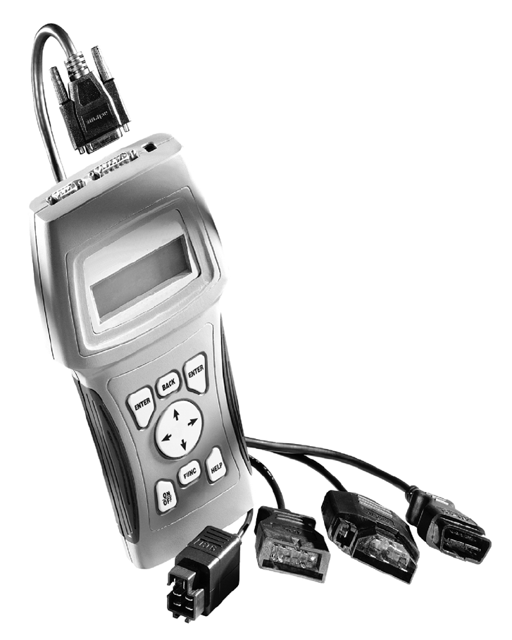
Section 3 – Using The Scan Tool THE SCAN TOOL B Serial Port (DB9 Male Connector) – provides a serial RS232 connection for a printer C D E F G H I J a b and for updating the software. DLC Port (DB15 Male Connector) – provides connection for vehicle interface. 12V Power Jack LCD Display – backlit, 4 line x 20 character with contrast adjustment. BACK key – goes to the previous screen or level. UP/DOWN arrows – scrolls UP or DOWN and moves the selection pointer (`).
Using The Scan Tool Specifications Display: Backlit LCD, 4 line, 20 column, contrast adjust Operating Temperature: 0 to 50°C (32 to 122°F) Storage Temperature: -20 to 70°C (-4 to 158°F) Internal Power: 6-AAA cells External Power: 7 to 16 Volts ✓ Most vehicle control modules require at least 8.0 V to operate properly. Power Dissipation: 3.5 Watts maximum Dimensions: Height Width 1.625" 41 mm Weight: 3.16 lbs (1432 g) 3 5.25" 133 mm Length 9.
Using The Scan Tool Display The scan tool uses a 4 line by 20 character, back-lit Liquid Crystal Display (LCD). The large viewing area displays messages, instructions, and diagnostic information. The contrast can be adjusted. Seven characters help you navigate and operate the scan tool: ? appears in upper right corner of display to indicate Help is available. ` identifies the selection.
Using The Scan Tool Power ✓ Refer to “Scan Tool Does Not Power Up” on page 9-1 if you encounter problems. Internal Batteries When the scan tool is not connected to the vehicle, the ON/OFF key turns ON the scan tool. Press and hold down the ON/OFF key for at least one second to turn ON the scan tool. To conserve battery power, the scan tool disables the display’s back-lighting and turns OFF after a period of inactivity. Each time the scan tool is powered up, the voltage of the batteries is checked.
Using The Scan Tool Scan Tool Setup Tool Setup allows you to change the measurement units and LCD contrast, turn beeper On/Off and display tool information. The settings remain until the internal batteries become discharged. Main Menu ` Vehicle Diagnosis Tool Setup Tool Self-Tests ? [ ~ Setup Tool ` 1)English/Metric 2)Display Contrast 3)Beeper [ ~ Measurement Units To change the measurement units, use the UP/DOWN arrow keys to select English/Metric and press ENTER.
Using The Scan Tool Compatible Printers The printer must have a serial RS-232 interface circuit and be compatible with the Epson FX format. The following printers are recommended: ❒ ❒ ❒ ❒ 3 Seiko DPU-414 Kodak DICONIX 180si (serial printer model) Lexmark Model 2480 with optional serial interface (p/n 12T0154) Panasonic KX-P1131 printer Cabling ❒ Type: A standard RS-232 type cable. ❒ Scan Tool end: DB9F (female) connector. ❒ Printer end: • Use a DB9M (male) connector for the Seiko and DB9 Kodak printers.
Using The Scan Tool Refer to the printer manual for the settings. The changes made reside in the tool even when the tool is turned off. Tool settings are as follows. Defaults are in [ . . . ] ❒ ❒ ❒ ❒ Baud Rate: [9,600], 1200, 2400 Stop Bits: [1 Bit], 2 bits Parity: [None], Odd, Even Printer Speed: [Fast], Slow Press ENTER after selecting each setting. Follow the instructions displayed on the screens. For the printer to work properly, the tool and the printer must be set to the same configuration.
Using The Scan Tool CONNECTING THE SCAN TOOL To diagnose a vehicle, connect the DLC and power adapter (if applicable) to the scan tool. Refer to “Diagnostic Link Connectors (DLC)” on page 2-5 of Getting Started. Diagnostic Connector If you just want to power up the tool to do its self-tests, code lookup, review or printing data from the last vehicle tested, then you do not need to attach the cable to the Data Link Connector. The internal battery provides power for this.
Using The Scan Tool Changing the Vehicle Changing vehicles erases all data stored in the tool. The default is YES. Picking New Vehicle Erases All Stored Data. Continue? NO Press ENTER to continue. Four Vehicle Options are available: Global OBD II, Domestic Vehicles, European Vehicles, Asian Vehicles. Global OBD II does not require additional information and takes you directly to the function list. The other three require additional information so that the tool can communicate with the vehicle.
Using The Scan Tool The menus provide a list of choices and reference the vehicle’s VIN where applicable. The VIN is visible from outside the vehicle by looking through the base of the front windshield at the top of the dashboard on the driver’s side. Because manufacturers use different VIN schemes, the tool will indicate which digit of the VIN to locate for information such as Year, Make and Engine. 3 Use UP/DOWN arrow keys to move through the list.
Using The Scan Tool User Interface The scan tool is designed to be as intuitive as possible. All menu and lists operate the same way. Use the UP/DOWN arrow keys to move UP/DOWN through the display or move the cursor (`) to a selectable item. Press the ENTER key to select the function or item. To return to previous screens, press the BACK key. This information can be viewed on the scan tool by pressing the HELP key after powering up the scan tool.
Using The Scan Tool Entire Data List The Entire Data List shows all supported parameter identification (PID) data for the vehicle being tested. When the scan tool makes a recording, the data from all supported PIDs are stored in the scan tool. Select Data To View ` Entire Data List Custom Data List View Data Setup ~ Custom Data List The Custom Data List allows you to select certain PIDs from the Entire Data List, such as those PIDs that pertain to a specific driveability symptom or system.
Section 4 – Global OBDII Diagnostics The first time scan tool links to the vehicle, communication is automatically detected, and is used until scan tool is turned OFF or another vehicle is diagnosed. ✓ If an Error Message displays, make sure OBDII connector is attached, and ignition key is ON. Cycle ignition key to OFF for 10 seconds, then ON. This may be required to reset computer. If required, select YES to try again. If problem still exists, refer to “Error Messages” on page 9-2.
Global OBDII Diagnostics Vehicles may support two types of I/M Readiness: ❒ SINCE DTCs CLEARED shows monitor status since DTCs were erased. ❒ THIS DRIVING CYCLE shows monitor status since current drive cycle started. If monitors are not supported for THIS DRIVING CYCLE, Scan Tool only shows monitors for SINCE DTCs CLEARED with no header on line 1. Select I/M Readiness from OBDII Function List menu and press ENTER.
Global OBDII Diagnostics READ CODES The Read Codes function gets Diagnostic Trouble Codes (DTCs) from vehicle’s computer module(s). Read Codes function can be done with Key On Engine Off (KOEO) or Key On Engine Running (KOER). These codes cause computer to light Malfunction Indicator Lamp (MIL) when emission-related or driveability fault occurs. MIL is also known as “service engine soon” or “check engine” lamp. Select Read Codes and press ENTER. Scan Tool gets DTCs stored in vehicle’s computer module(s).
Global OBDII Diagnostics PENDING CODES Pending Codes are also referred to as “continuous monitor” and “maturing codes”. An intermittent fault causes computer to store a code in memory. If fault does not occur within 40 warm-up cycles, code clears from memory. If fault occurs a specific number of times, code matures into a DTC and MIL lights or blinks. This function can be done with KOEO or KOER. Select Pending Codes and press ENTER key.
Global OBDII Diagnostics ERASE CODES The Erase Codes function deletes DTCs from vehicle’s computer memory. It may also erase Freeze Frame, O2 Sensor Data, System Monitors, and On-Board Monitor test results. Perform this function only after systems have been checked completely and DTCs have been documented. This function should be performed with KOEO — Do not START engine. After servicing vehicle, erase stored DTCs and verify no codes have been reset.
Global OBDII Diagnostics VIEW DATA The View Data function allows “real time” viewing of vehicle’s Parameter Identification (PID) data. As computer monitors vehicle, information is simultaneously transmitted to scan tool. Apart from Read Codes, View Data is the most useful diagnostic function for isolating cause of a vehicle operation problem. Viewing data is also used for observing sensor data and status of switches, solenoids, and relays. Select View Data from OBDII Function List and press ENTER.
Global OBDII Diagnostics If one or more control modules stops responding, tool displays message that it is not responding. Module $1F is not Responding. Continue Without it? Yes ~ If choosen to continue, dashes will replace data in right-hand column. If NO is selected, then scan tool attempts to reestablish communication with that module. Press FUNC to return to OBDII Function List.
Global OBDII Diagnostics O2 MONITOR TEST ✓ The O2 Monitor Test is NOT AN ON-DEMAND TEST. O2 sensors are NOT tested when selected via the menu. O2 sensors are tested when engine operating conditions are within specified limits. ✓ If vehicle communicates using a Controller Area Network (CAN), O2 Monitor tests are NOT supported by vehicle. A message is displayed. See Diagnostic Monitor Test to see O2 Monitor data.
Global OBDII Diagnostics Select Oxygen Sensor information to view. Select O2 Sensor ` 02 BANK1 Sensor1 ~ ✓ The O2 sensors located upstream (before catalyst) may perform differently than ones located downstream (after catalyst). View test information by using UP and DOWN arrows. 02 Bank1 Sensor1 RICH-LN Thresh 0.450(V) MOD$10 [ ~ 4 Press BACK key to return to O2 Sensor Tests menu or press FUNC to return to OBDII Function List.
Global OBDII Diagnostics Select Diag Mon Test from OBDII Function List and press ENTER. Applicable tests are displayed . Select a test and press ENTER. OBDII Function List 7)O2 Monitor Test ` 8)Diag Mon Test 9)On-Board Systems ? ] [ ~ Diag Mon Data Avail ` $01 $05 [ $10 ~ Non-CAN Vehicles OR Diag Mon Data Avail ` O2 Sensor B1S1 Catalyst B1 [ EVAP (0.
Global OBDII Diagnostics If additional tests are present use UP/DOWN arrow keys to view test results. Refer to appropriate vehicle service manual for test IDs and definitions. Press BACK key to return to the Diag Mon Test menu or press FUNC key to return to OBDII Function List. ON-BOARD SYSTEMS The On-Board Systems test allows scan tool to control operation of vehicle components, tests or systems. Some manufacturers do not allow tools to control vehicle systems.
Global OBDII Diagnostics RECORD DATA The Record Data function records PIDs while vehicle is parked or being driven. This function is mainly used for diagnosing intermittent driveability problems that cannot be isolated by any other method. Two people MUST be in vehicle when driving — one to drive and the other to operate scan tool. Select Record Data from OBDII Function List and press ENTER.
Global OBDII Diagnostics Once trigger method is selected, scan tool will begin recording data. When trigger event (either a DTC or a Press of ENTER key) occurs, time is recorded and data from last five frames are saved. Data will continue to be saved until either record memory is full or technician presses ENTER. ** INITIALIZING ** PRETRIG FRAME:-5 BACK To Exit ~ Press BACK key twice to return to OBDII Function List. ✓ **Ready To Record** Press ENTER Anytime To Start Recording.
Global OBDII Diagnostics VEHICLE INFO The Vehicle Info function allows scan tool to request vehicle’s VIN number, calibration ID(s) which identifies software version in vehicle control module(s), Calibration Verification Numbers (CVN(s)) and In-Use Performance tracking. 44 ✓ Vehicle Info function applies to model year 2000 and newer OBD II compliant vehicles. ✓ ✓ The Scan Tool cannot verify if data is correct for scanned vehicles. ✓ ✓ The CVN calculation may take several minutes.
Global OBDII Diagnostics Scan Tool displays in-use performance tracking data, if supported by vehicle. In following examples, Module 10 returned data. Scroll down to view information. IPT Counts MOD $10 ? OBDCOND(cnts) 2 IGNCNTR(cnts) 22 CATCOMP1(cnts) 35~ Abbreviations and names for In-Use Performance Tracking Data supported by Scan Tool are shown below. Not all data is supported by all vehicles.
Global OBDII Diagnostics MODULES PRESENT The Scan Tool identifies the module IDs and communication type for OBDII modules in the vehicle. Select Modules Present from the OBDII Function List and press ENTER.
Global OBDII Diagnostics NOTE: Since CAN vehicles use module ID’s larger than 2 digits, the Scan Tool will assign a 2 digit module ID to be used in place of the actual CAN module ID. The Module ID assigned for the CAN Module ID will be used in all functions of Scan Tool. •ISO 14230-4 protocol will be shown as K2K (Keyword 2000.
Global OBDII Diagnostics REVIEW DATA The Review Data function allows operator to review information stored in Scan Tool’s memory. Scan tool does not require power from vehicle to do this function. Internal battery power can be used. Select Review Data from OBDII Function List and press ENTER. OBDII Function List ` 13)Review Data 14)Print Data 15)Code Lookup ? ] [ ~ Scan tool displays Review Data screen with nine types of data to review.
Global OBDII Diagnostics Scan tool displays a NO RECORDING PRESENT message if recording does not exist. Otherwise, press ENTER to play back recording. Scan tool plays back Entire Data List or Custom Data List, depending on how data was recorded. The Playback has three lines of data and one line for frame number and timestamp (in seconds). MIL STATUS($10) MIL STATUS($1A) ABSLT TPS(%)($10) FRAME: 1 TM: 4.4 ON ON 35[ ~ Negative frames and timestamps indicate data recorded before trigger event.
Global OBDII Diagnostics PRINT DATA The Print Data function allows the printing of diagnostic information stored in Scan Tool. OBDII Function List 13)Review Data ` 14)Print Data 15)Code Lookup ? ] [ ~ The scan tool’s internal battery power can be used to print data. Select Print Data and press ENTER key. Scan tool informs of printer settings (Custom or Default), then asks if setting need to be changed. 44 Tool Set To Default ? Printer Settings.
Global OBDII Diagnostics Press ENTER to return to Select Print Data screen. Either select another item to print or press BACK to return to OBDII Function List All Data Has Been Sent To Printer Press ENTER To Cont. ~ Printing Playback Data When printing playback data, Start Frame and End Frame need to be defined. After selecting Playback and pressing ENTER, Start Frame screen shows the earliest possible frame. Use UP/DOWN arrow to change frame number and press ENTER.
Global OBDII Diagnostics CODE LOOKUP Code Lookup is used to look up definitions of Diagnostic Trouble Codes (DTCs) stored in Scan Tool. Scan tool does not require power from vehicle to perform this function, the internal battery power can be used. To look up DTC definitions, select Code Lookup from OBDII Function List. When entering codes, all characters must be entered. Only one character can be changed at a time. ❒ Use LEFT/RIGHT arrow keys to scroll to desired character.
Section 5 – GM Diagnostics ✓ If the Scan Tool displays an Error Message, make sure the cables and adapters are securely attached and the ignition key is ON. Cycle the ignition key to OFF for 10 seconds, then ON. Attempt the test selected again. If the problem remains, refer to “Error Messages” on page 9-2. GM HISTORIC (OBD I) DIAGNOSTICS ✓ Some 1994 and 1995 vehicles use the 16-pin OBD II connector, but are not OBD II compliant. They still use the OBD I application software.
GM Historic (OBD I) Diagnostics Select Read Codes from the GM Function List and press ENTER. The tool will retrieve the DTCs. GM Function List ` 1)Read Codes 2)Erase Codes 3)View Data ? [ ~ One of two screens displays: If the diagnostic checks are working correctly and no DTCs have been stored in vehicle’s memory, a SYSTEM PASS message displays. If not, the tool displays a screen indicating the number DTCs. System Pass: No Faults Detected. ~ Use the UP/DOWN arrow keys to scroll through the codes.
GM Historic (OBD I) Diagnostics A message appears asking if you are sure. Press LEFT/RIGHT to move the brackets to the desired response and press ENTER. Erase Codes? Are You Sure? Yes Selecting NO and pressing ENTER returns you to the GM Function List. Selecting YES displays a screen prompting you to turn ignition ON. Turn ignition key ON. Engine can be off or running. Press ENTER to continue. A message confirming that the Erase Codes command was successful displays.
GM Historic (OBD I) Diagnostics View Data The View Data function allows the user to view the vehicle Parameter Identification Data (PIDs) in real time. As the PCM monitors PIDs, they are simultaneously transmitted to the scan tool. The PIDs are continuously updated at the PCM’s rate. In addition to reading codes, View Data is the most useful diagnostic function for isolating the cause of a vehicle operation problem.
GM Historic (OBD I) Diagnostics Record Data The Record Data function records vehicle PIDs (Parameter Identification Data) while the vehicle is parked or being driven. This function is mainly used for diagnosing intermittent driveability problems that cannot be isolated by any other method. The tool records data based on time (5 frames prior to the start of the recording, and for a duration after). The time after depends on the vehicle data rate.
GM Historic (OBD I) Diagnostics If Manual Trigger is selected, press ENTER to begin recording. Trigger On Codes will not show this screen. The function runs automatically and stops when the tool’s memory is filled. When done, the tool prompts you to “PLAY THE RECORDING?” Select YES to review the data now or NO to review it later using the next function, Review Data. **Ready To Record** Press ENTER Anytime To Start Recording. ~ **Recording Data** Stops Automatically When Memory is Full.
GM Historic (OBD I) Diagnostics Playback The Playback function is used to playback a Record Data recording. This function is very similar to View Data. The only difference is that View Data is a real time viewing of PIDs, while Playback is a viewing of previously recorded PIDs. Select Playback from the Review Data screen and press ENTER: Review Data 1)DTC (Codes) ` 2)Playback ? ~ ✓ If a recording does not exist in the tool memory, then the tool will display a “NO RECORDING PRESENT” message.
GM Historic (OBD I) Diagnostics Field Service Field Service is a special diagnostic mode to monitor fuel system operation and read DTCs. Some GM service manuals may refer to this mode as the Field Service Mode Check. This mode works on vehicles equipped with a 12-pin ALDL connector with a wire present in Pin-B, Diagnostic or Test Enable. The scan tool enters this mode by grounding Pin-B: shorting Pin-B to Pin -A (ground).
GM Historic (OBD I) Diagnostics KOEO Procedure In the KOEO Procedure, Field Service can check relays, solenoids and the idle speed motor, and obtain DTCs using the CHECK ENGINE light. 1) Turn ignition Key ON but DO NOT Start Engine. 2) On scan tool, place Field Service On. 3) The Check Engine light will begin to flash codes. Each DTC is displayed three (3) times. The DTCs are displayed starting with the lowest numbered one.
GM Historic (OBD I) Diagnostics KOER Procedure With the engine running, the Field Service mode can be used to measure base timing, check open loop/closed loop operation, and determine if the engine is running rich or lean. 1) Engage parking brake and block drive wheels. 2) Verify engine is cold. If engine is hot or warm, allow it to cool. 3) On scan tool, place Field Service On. 4) Start engine and place transmission in Park or Neutral. The Check Engine light will flash once.
GM Enhanced (OBD II) Diagnostics GM ENHANCED (OBD II) DIAGNOSTICS IMPORTANT This system applies to GM vehicles manufactured from 1996 to present. Some GM vehicles in 1994 and 1995 were equipped with this system. Refer to “Appendix A - Data Link Connectors". GM vehicles manufactured from 2002 to present automatically use Global OBD II Diagnostics. ✓ If an Error Message displays, make sure the OBD II connector is securely attached, and the ignition key is ON.
GM Enhanced (OBD II) Diagnostics Not all GM vehicles support DTC status. Some only use the Global OBDII Read Codes command. For a description of these screens, refer to the Global OBDII section of the manual. • History Codes — intermittent codes placed in the vehicle’s memory when the trouble originally occurred, and will remain there even if the trouble has been corrected. If no trouble after 50 engine warm-up cycles, the DTC will be erased.
GM Enhanced (OBD II) Diagnostics Use the UP/DOWN arrow keys to view the DTCs. Use the LEFT/RIGHT arrow keys to toggle the DTC definition and status screen. ENG CURR P0201 Injector Circuit Open Cylinder 1 [ ENG CURR P0201 MIL REQUESTED Since IGN FAIL Since Clear P/F [ Engine or Powertrain Module Press FUNC to return to the GM Function List. Pending Codes Refer to “Pending Codes” on page 4-4 of Global OBDII Diagnostics.
GM Enhanced (OBD II) Diagnostics GM arranges the PIDs in four groups: ❒ Analog: viewing of analog sensor ❒ ❒ ❒ ✓ Select Pid Group ` Analog O2 Misfire ? signals, such as measured voltage from O2 sensors, temperature sensors, and air flow sensors. O2: viewing oxygen sensor information. Misfire: viewing of cylinder misfire information. Digital: viewing of switches, solenoids and relays. [ ~ Some GM trucks manufactured in 1996 – 1998 have only one PID group.
GM Enhanced (OBD II) Diagnostics View Freeze Data When an emission-related fault occurs, certain vehicle conditions are recorded by the on-board computer. This information is referred to as a Freeze Frame data. The information is a “snapshot” of the operating conditions at the time of a fault. This data can be overwritten by faults with a higher priority. ✓ Only one Freeze Frame can be kept per module. Switching from Engine to Transmission will overwrite Data.
GM Enhanced (OBD II) Diagnostics Record Data Refer to “Record Data” on page 4-12 of Global OBDII Diagnostics. GM groups the PIDs into four categories: ❒ Analog: viewing of analog sensor signals, such as measured voltage ❒ ❒ ❒ ❒ ✓ ✓ from O2 sensors, temperature sensors, and air flow sensors. O2: viewing oxygen sensor information. Misfire: viewing of cylinder misfire information. Digital: viewing of switches, solenoids and relays. Module: viewing of engine, transmission or transfer case information.
GM Enhanced (OBD II) Diagnostics Print Data The Print Data function is used to print diagnostic information on Scan Tool. To Print vehicle’s recorded PIDs, select Print Data from the Powertrain List and press ENTER. Select the recording you wish to print. TRANS Digital means that you made a Digital Group recording from the Transmission Module.
GM Enhanced (OBD II) Diagnostics 5 5 – 18 • • • • • • • • • • • • • • • • • • • • • • • • • • • • • • • • • • • • • • • • • • • • • • • • • • • • • • •
Section 6 – Ford Diagnostics FORD HISTORIC SELF-TEST ROUTINES Due to different processor calibrations, the Ford Function List for a particular vehicle may or may not appear as shown. Based on the vehicle information entered at the Vehicle Setup menu, the tool automatically recognizes the computer system installed. If the function is not supported by the vehicle, than the scan tool does not display it. ✓ ✓ ✓ Ford vehicles manufactured from 2002 to present automatically use Global OBD II Diagnostics.
Ford Historic Self-Test Routines Select Read KOEO Codes from the Ford Function List and press ENTER. Ford Function List ? ` 1)Read KOEO Codes 2)Read KOER Codes [ 3)Review Codes Select Fast Codes or Slow Codes and press ENTER. Follow the instructions step-by-step. 1) Set Parking Brake. 2) Put Transmission In Park Or Neutral. 3) Turn A/C Off. 4) Start Engine — Let Idle Until Hot. 5) Turn Ign Key Off. 6) Wait 10 Seconds. Turn Key On-Engine Off. Do Not Start Engine.
Ford Historic Self-Test Routines ✓ Continuous Memory Codes (codes set previously under normal driving conditions) are available after reading KOEO Codes. They are indicated as Memory Codes by the scan tool and are transmitted after KOEO Codes. After viewing and noting the KOEO codes, use the DOWN arrow key to view Continuous Memory codes. When done, press FUNC to return to the Ford Function List.
Ford Historic Self-Test Routines Fast or Slow Codes Select Fast Codes or Slow Codes and press ENTER. Follow the instructions step-by-step. Failure to perform these steps may set a false DTC in the PCM — observe the display. Select Code Type ` 1)Fast Codes 2)Slow Codes 3)Computed Timing 1) Set Parking Brake. 2) Transmission In Park Or Neutral. 3) Turn A/C Off. 4) Start Engine — Let Idle Until Hot. 5) Turn Ign Key Off. 6) Wait 10 Seconds. Start Engine — Let Idle.
Ford Historic Self-Test Routines If no problems exist, Code 11 or 111 will be displayed. KOER Code 111 System Pass Code No Faults Detected [ During KOER Test ~ If vehicle problems exist, codes are set. KOER Code 326 PFE/DPFE EGR Sensor] Below Min. Voltage [ Use UP/DOWN arrow keys to view codes. Write down codes for reference. ~ When done, press FUNC to return to the Ford Function List screen.
Ford Historic Self-Test Routines If a KOER code of 98 or 998 is detected, then the fault must be fixed before performing this function. Press the BACK key to return to the Ford Function List. Otherwise, the timing remains fixed for 90 seconds to allow you to measure it with the Timing Light. Can't Run Timing Check. Code 98/998 Detected. Fix Fault & Redo Timing Check~ Timing Is Now Fixed At Base Timing Plus 20 Deg. (+/- 3 deg).
Ford Historic Self-Test Routines Erase Codes The vehicle service manual may recommend erasing Continuous Memory Codes from vehicle’s memory, and then driving vehicle to duplicate the malfunction before beginning a diagnostic test. If KOEO codes were read using Fast Codes, the memory codes have already been erased. Only Continuous Memory Codes can be erased from the vehicle without repairing the fault. To remove KOEO and KOER Codes, the fault must be repaired since they only exist when a fault exists.
Ford Historic Self-Test Routines MECS Erase Codes Select Erase Codes from the Ford Function List and press ENTER. Press ENTER after each message. Only Memory Codes Are Erasable! Press ENTER to Cont~ ! CAUTION Ford Function List 3)Review Codes ` 4)Erase Codes 5)Wiggle test ? ] [ ~ To Erase KOEO And KOER Codes, You Must Fix Cause of Code. Press ENTER to Cont~ Never Lay Tools On Vehicle Battery. Tools May Create Shorts And Cause Harm To User And Damage To Tools, Battery And Electrical System.
Ford Historic Self-Test Routines Either a KOEO or KOER Wiggle Test can be run. If the vehicle problem occurs while driving, the KOER Wiggle Test is recommended. After selecting, press ENTER. Select Wiggle Test ` 1)KOEO Wiggle Test 2)KOER Wiggle Test ~ Follow the tool’s instructions. 1) Set Parking Brake. 2) Put Transmission In Park Or Neutral. 3) Turn A/C Off. 4) Turn Ign Key Off. Wait 10 Seconds. 5) KOEO: Turn Key On. Engine Off. Do Not Start Engine. 6) KOER: Turn Key On. Engine On and let Idle.
Ford Historic Self-Test Routines Output Switch Test (EEC-IV Vehicles) The Output Sw (Switch) Test, also known as the Output State Check, is used to check the operation of the computer-controlled relays and solenoids on EEC-IV vehicles. The user can troubleshoot circuits using a voltmeter to measure voltage at the relays and solenoids in both energized and non-energized conditions. All measurements should be recorded for reference. ✓ ✓ Fuel injectors are NOT energized during this test.
Ford Historic Self-Test Routines Cylinder (Cyl) Balance Test (EEC-IV Vehicles) ✓ The Cyl Balance Test is only applicable to engines equipped with EEC-IV Sequential Electronic Fuel Injection (SEFI or SFI) . The Cyl Balance Test identifies a weak cylinder(s) on EEC-IV vehicles. A weak cylinder may be caused by low compression, poor valve seating, fouled spark plugs, damaged fuel injectors, and other cylinder faults. The PCM shuts off the fuel supply to each cylinder and measures the RPM drop.
Ford Historic Self-Test Routines If no DTC is present, continue with the paragraph following the note below. If any DTC(s) are present, the Cyl Balance Test stops and the tool displays the screen to the right. Correct All Faults Rerun Test View Fault Codes? NO ~ Select YES to review the DTC(s), then turn engine off. Record them and make repairs before repeating the Cyl Balance Test. In the next step, Do Not touch any vehicle or tool keys while the test is running. Allow engine to idle.
Ford Historic Self-Test Routines IVSC-Speed Ctrl (EEC-IV Vehicles) The IVSC-Speed Ctrl (Integrated Vehicle Speed Control) is Ford’s computerized cruise control system on EEC-IV vehicles. It is controlled by the PCM and contains a dedicated network of sensors, switches, and actuators. Both KOEO and KOER Codes exist for this test. The tool provides the ability to diagnose problems by reading DTCs. Select IVSC-Speed Ctrl from the Ford Function List and press ENTER. The sub-menu Select IVSC Test is displayed.
Ford Historic Self-Test Routines Use the UP/DOWN arrow keys to scroll through the KOEO Code listing. Be sure to write down any codes for reference. IVSC KOEO Code 568 SCVAC Failure: Speed Control Vacuum Circuit Failure ~ Reading IVSC KOER Codes Select Read KOER Codes from the sub-menu and press ENTER. To retrieve codes, follow the instructions on the tool screen as follows: 1) Set Parking Brake. 2) Put Transmission In Park Or Neutral. 3) Turn A/C Off. 4) Start Engine — Let Idle Until Hot.
Ford Historic Self-Test Routines STAR Test Mode (EEC-IV, MECS and MCU Vehicles) The STAR Test Mode can be used to retrieve DTCs from the PCM or other STAR (Self-Test Automatic Readout) compatible controllers installed in the vehicle. STAR Test Mode functions largely the same way and serves the same purpose as running KOEO and KOER tests. It is generally used as a last resort to check for DTCs in systems which may not be covered by KOEO and KOER testing (i.e. - Computer Ride Control suspension systems).
Ford Historic Self-Test Routines After all codes are sent, the series will repeat once and then stop. An example is shown below.
Ford Historic Self-Test Routines Press ENTER to display the definition(s) for that number. More than one definition may be available for the DTC number entered. Use the UP/DOWN arrow keys to view them. KOER Code: Idle Switch CKT Grounded 058 ] [ ~ If the definition does not exist for the vehicle, then a message displays. Press ENTER to return to the Lookup Code screen or press the FUNC key to return to the Ford Function List menu.
Ford Historic Self-Test Routines After selecting View Data, a Select Data to View screen will allow you to customize the function. See “Viewing Data” on page 3-11 of Using The Scan Tool for Entire or Custom Data Lists. Select Data To View ` 1)Entire Data List 2)Custom Data List ~ After selecting the Entire Data List or Custom Data List, press ENTER. Once the communication link has been established, start the engine and let idle.
Ford Historic Self-Test Routines Once the communication link has been established, you are ready to record data. ! CAUTION Never operate the tool while driving. Have another person assist with the operation of the tool. Recording starts when the ENTER key is pressed. **Ready To Record** Press ENTER Anytime To Start Recording. Stops Automatically ~ The tool records for a varying time duration.
Ford Historic Self-Test Routines After selecting the data List type, press the ENTER key to start playing back the recorded data. BOO-Brake Sw Canst Purge ECT Sensor(v) Frame:16 Time: ON ? ON ] 3.3 [ 24.7~ The Playback Data screen has a Vehicle Data List header that marks the beginning of the data list. On the Playback Data screen, lines 1-3 are used to display vehicle data parameters. The fourth line displays the Frame number and Time in seconds.
Ford Enhanced (OBD II) Diagnostics FORD ENHANCED (OBD II) DIAGNOSTICS IMPORTANT This system applies to Ford vehicles manufactured from 1996 to present. Some vehicles in 1994 and 1995 were equipped with the EEC-V system. Refer to “Appendix A - Data Link Connectors". Ford vehicles manufactured from 2002 to present automatically use Global OBD II Diagnostics.
Ford Enhanced (OBD II) Diagnostics If DTCs are found, use the DOWN arrow key to view them. Write down the DTCs for reference and then press BACK to return to the Ford Function List. DTCs Found: 3 Use [ To View DTCs Write Down Codes For Reference ~ DTC P0107 MAP/BARO Circuit Low Input Read All DTC [ ~ The Read All DTC function retrieves all DTCs (MIL, non-MIL, Pending and Memory) stored in the vehicle’s computer module(s). This function can be performed with the KOEO or KOER.
Ford Enhanced (OBD II) Diagnostics Erase Codes Refer to “Erase Codes” on page 4-5 of Global OBDII Diagnostics. Perform this KOEO. After erasing the DTCs, verify new ones have not been set using the Read All DTC function. IMPORTANT Until all monitors have ran the absence of a Diagnostic Trouble Code (DTC) does not mean the fault has been fixed. View Data The View Data function allows you to view the vehicle’s Parameter Identification (PID) data in real time.
Ford Enhanced (OBD II) Diagnostics After making a selection, press ENTER to establish a communication link. Multiple PIDs may be sent if the vehicle is equipped with more than one computer module — Powertrain Control Module (PCM), Transmission Control Module (TCM), etc. The scan tool identifies them by their identification names (ID) assigned by the manufacturer (i.e. $40 or $1F).
Ford Enhanced (OBD II) Diagnostics Select Quick Test from the Ford Function List and press ENTER. The list of available tests are displayed. If testing a 7.3L powerstroke diesel, more tests become available. Ford Function List ? 6)View Data ] 7)View Freeze Data[ ` 8)Quick Test ~ Quick ` KOEO KOER KOEO Tests On Demand On Demand Output State ~ KOEO On Demand The KOEO On Demand is a functional test of the computer modules and system with the Key ON – Engine OFF (KOEO).
Ford Enhanced (OBD II) Diagnostics If no Codes are read, the System Pass screen displays. System Pass: No DTCs Found ~ If problems exist, the screen indicates that codes have been read. Use UP/DOWN arrow keys to view them. Press the FUNC key to return to the Ford Function List. DTCs Found: 2 Use [ To View DTCs Write Down Codes For Reference.
Ford Enhanced (OBD II) Diagnostics After pressing ENTER to continue, the KOER self-tests begins. The tool prompts you to: Test In Progress Approximate Time Left 4:00 Press BACK to Quit ~ ❒ Work Steering Wheel ❒ Pump Brake Pedal ❒ Cycle OD (overdrive) Cancel Switch (on some Automatic Transmissions.) When the test is done, the DTCs found display on the screen. Use UP/DOWN arrow keys to view Codes. If no codes are read, the System Pass screen is displayed.
Ford Enhanced (OBD II) Diagnostics The Output State Options are displayed. The fourth option is “High Speed Fan.” Select an option and press ENTER. ✓ Output ` 1)All 2)All 3)Low State Option Off But Fans/Inj [ Speed Fan ~ Listen for devices turn on and off. After a brief Command Sent screen, an Output State screen is displayed for the duration of the test. Select CHANGE to toggle the state to On/Off or QUIT to return to the Quick Tests screen.
Ford Enhanced (OBD II) Diagnostics KOER Glow Plug The KOER Glow Plug is an on-demand test which activates the glow plug relay and detects any difference in the amount of current between both banks of glow plugs. DTCs returned from the test indicate which bank has failed glow plugs or failed wiring. Exhaust gases are harmful or FATAL. Always operate vehicle in a well-ventilated area. The KOER glow plug test is done with the engine running. Do not over-rev engine. Observe all safety precautions.
Ford Enhanced (OBD II) Diagnostics During the test, the engine will emit smoke, and the RPM varies with each check (there is no audible difference in RPM if a bad/weak cylinder is detected). Exhaust gases are harmful or FATAL. Always operate vehicle in a well-ventilated area. The KOER cylinder contribution test is done with the engine running. Set the parking brake and place the transmission in DRIVE (Automatic Transmissions only). Do not over-rev engine. Observe all safety precautions. Select KOER Cyl.
Ford Enhanced (OBD II) Diagnostics Select KOER Switch from the Quick Tests screen. Press ENTER to begin the test. Quick KOER KOER ` KOER Tests Glow Plug Cyl. Cont. Switch ? ] ~ Exhaust gases are harmful or FATAL. Always operate vehicle in a well-ventilated area. The KOER switch test is done with the engine running. Do not over-rev engine. Observe all safety precautions. Follow all user interaction required to run the KOER Switch Self-Test. The tool will display a prompt when action is required.
Ford Enhanced (OBD II) Diagnostics O2 Monitor Test Refer to “O2 Monitor Test” on page 4-8 of Global OBDII Diagnostics. Diagnostic Monitor Tests Refer to “DIAGNOSTIC MONITOR Tests” on page 4-9 of Global OBDII Diagnostics. On-Board Systems Refer to “On-Board Systems” on page 4-11 of Global OBDII Diagnostics. Record Data Refer to “Record Data” on page 4-12 of Global OBDII Diagnostics.
Section 7 – Chrysler Diagnostics ✓ ✓ ✓ ✓ Due to different processor calibrations used, the function list for a particular vehicle may or may not appear as shown. Based on the vehicle information entered at the Vehicle Setup menu, the tool recognizes the computer system installed. If an Error Message displays, make sure the adapter cable is securely attached, and the ignition key is ON. Cycle the ignition key to OFF for 10 seconds, then ON. This may be required to reset the computer.
Chrysler Diagnostics Use the UP/DOWN arrow keys to scroll through the codes. Write down the codes for reference or print them later. ENG: 31/P0443 EVAP Purge Solenoid Circuit ~ The DTCs are categorized by ENG (engine) or TRANS (transmission). The Chrysler MIL code (3-digit) and SAE code (5-digit) follow on the first line. ENG: 31/P0443 EVAP Purge Solenoid Circuit TRANS: 18/P1792 Battery ] Disconnected [ (In Last 50 Cycles) ~ ~ There may be times where only one or both display.
Chrysler Diagnostics Use the UP/DOWN arrow keys to scroll through the codes. Note the codes and press FUNC to return to the Chrysler Functions list. ENG: 14/P0107 MAP Voltage Too Low ~ Use the UP/DOWN arrow keys to scroll through the codes. Write down the codes for reference or print them later. ENG: 31/P0443 EVAP Purge Solenoid Circuit ~ The DTCs are categorized by ENG (engine) or TRANS (transmission). The Chrysler MIL code (3-digit) and SAE code (5-digit) follow on the first line.
Chrysler Diagnostics A message confirms the codes are erased. Press ENTER to return to the Chrysler Functions menu. Codes Erased. VIEW DATA The View Data function allows the mechanic to view the vehicle’s parameter identification data (PIDs) in real time. As the PCM monitors the PIDs, they are sent to the scan tool. Apart from Read Codes, View Data is the most useful diagnostic function for isolating the cause of a vehicle operation problem.
Chrysler Diagnostics FREEZE FRAME ✓ Available for 1999 and newer vehicles only. When an emission-related fault is detected, certain vehicle conditions at the time fault(s) were set and are recorded by the PCM. This is referred to as a Freeze Frame. The information is a “snapshot” of the engine operating conditions at the time of a fault. This data can be overwritten by faults with a higher priority. Turn ignition key On - Engine can be OFF or Running.
Chrysler Diagnostics The Record Data function allows diagnosis of an intermittent problem by analyzing data leading up to the problem, during the problem, and possibly after the problem, depending on duration. Select Record Data from the Chrysler Functions list and press ENTER. Follow all instructions on the display. ✓ ? ] [ ~ The tool can maintain only one recording at a time. Be sure to thoroughly review the old recording before erasing it.
Chrysler Diagnostics If Trigger On Codes was selected, then the scan tool triggers when a DTC is stored in the vehicle. Press the BACK key twice to return to the Chrysler Functions menu. The scan tool recording time varies. A recording consists of 5 frames of data prior to the trigger and several frames after the trigger. The amount of PIDs recorded determine the number of frames. After a recording, the Scan Tool displays a prompt to playback the recording.
Chrysler Diagnostics To finish testing switch, press the switch again. The switch status on the bottom should change if the switch is working. To test another switch, press the BACK key to return to the Select SW to Test screen. To return to the Chrysler Functions list, press the FUNC key. ACTUATOR TEST The Actuator Test is used to check the operation of many of the computer-controlled relays and solenoids. This is also helpful for checking voltages and output signals.
Chrysler Diagnostics IDLE SPEED TEST The Idle Speed Test is used to test the functionality of the vehicle idle speed control system. The test allows the user to enter the desired engine speed. The test vehicle should respond by matching the speed commanded. If the vehicle matches the demanded engine speed, the idle speed control system is functioning properly. Select Idle Speed Test from the Chrysler Functions list and press ENTER.
Chrysler Diagnostics One sensor will be displayed per screen. Use the UP/DOWN arrow keys to scroll through the supported sensors. The tool displays the status of the sensor. Viewing Sensor: ADPT FUEL(%) 5.00[ ~ Press the BACK or FUNC key to end the test and return to the Chrysler Functions list.
Chrysler Diagnostics Select Reset EMR Lamp from the Chrysler Functions list and press ENTER. Turn ignition key On, but do not start engine. Press ENTER to reset the EMR lamp. Chrysler Functions 9)Sensor Test 10)Controller Info ` 11)Reset EMR Lamp ? ] [ ~ EMR Lamp Is Reset. ~ Press the FUNC or BACK key to return to the Chrysler Functions list. SET BASIC TIME The Set Basic Time function is used when checking basic timing. This feature suspends spark scatter at idle.
Chrysler Diagnostics ✓ Set Sync Mode is available on 3.9L, 5.2L and 5.9L engines only. When returning to the Chrysler Functions list, timing will remain fixed. This allows the mechanic to use the Sensor Test function and read sensor data. To restore timing, the Abolish Request mode must be selected from the Select Request Mode menu. Depending on the Request Mode sent to the PCM, the tool will display the following messages: • Basic Timing Has Been Abolished. • Basic Timing Has Been Initiated.
Chrysler Diagnostics Use the UP/DOWN arrow keys to view the recorded PID data of each frame. The end of the list is reached when only the ] (up) icon is visible. Use the LEFT/RIGHT arrow keys to scroll back and forth through the frames. The RIGHT arrow key advances to the next frame, “wrapping around” to the earliest frame when the final frame is reached. The LEFT arrow key goes back to the previous frame, again “wrapping around” to the final frame.
Chrysler Diagnostics Press ENTER to display the definition. Both the MIL code and SAE code display with the definition when applicable. Eng: 46/P0401 EGR System Performance ~ The Chrysler MIL code (3-digit) and SAE code (5-digit) appear on the first line. There may be times where only one or both code types display. Dashes display if the DTC type does not exist. Eng: ---/P0400 EGR System Performance ~ Certain MIL codes may have more than one definition for the same vehicle.
Section 8 – Import Diagnostics IMPORT ENHANCED (OBD II) DIAGNOSTICS IMPORTANT This system applies to import vehicles manufactured from 1996 to present. Some import vehicles in 1994 and 1995 were equipped with this system. ✓ If an Error Message displays, make sure the OBD II connector is securely attached, and the ignition key is ON. Cycle the ignition key to OFF for 10 seconds, then ON. This may be required to reset the computer. If required, select YES to try again.
Import Enhanced (OBD II) Diagnostics Read Codes The Read Codes function retrieves Diagnostic Trouble Codes (DTCs) from the vehicle’s computer module(s). This function can be performed with the KOEO or KOER. These codes cause the computer to illuminate the Malfunction Indicator Lamp (MIL) when an emission-related or driveability fault occurs. The MIL is also known as the “service engine soon” or “check engine” lamp. Import Enhanced Read Codes reads DTC’s from modules.
Import Enhanced (OBD II) Diagnostics Pending Codes Refer to “Pending Codes” on page 4-4 of Global OBDII Diagnostics. Erase Codes The Erase Codes menu has a menu asking what module to erase codes for, if more than one module exists for this vehicle. View Data Refer to “View Data” on page 4-6 of Global OBDII Diagnostics View Freeze Data Refer to “View Freeze Data” on page 4-7 of Global OBDII Diagnostics O2 Monitor Test Refer to “O2 Monitor Test” on page 4-8 of Global OBDII Diagnostics.
Import Enhanced (OBD II) Diagnostics Print Data Refer to “Print Data” on page 4-20 of Global OBDII Diagnostics. Code Lookup Refer to “Code Lookup” on page 4-22 of Global OBDII Diagnostics.
Section 9 – Help & Troubleshooting HOW TO USE ON-LINE HELP The software contains On-Line Help for specific tool screens, functions, and error messages. When the icon (?) appears in the upper right-hand corner of the display, On-Line Help is available. To enter On-Line Help, press the HELP key. For the screen above, the help message would look like this The text in On-Line Help screens are in CAPITAL LETTERS.
Help & Troubleshooting PIN 4 (GND) PIN 2 (BAT+) PIN 6 (GND) PIN 16 (BAT+) LH DLC J1962 (OBD II) DLC Scan Tool does not power up. Is battery fully charged? Measure Voltage between BAT + and GND pins. NO Charge battery. NO Repair Ground circuit. Refer to a service manual. YES Measure resistance between GND pin and frame ground. Above 8V? NO less than 5 ohms? YES Contact Customer Service Center. YES Open exists in power circuit. Check for a blown fuse or an open wire.
Help & Troubleshooting Check the following if an error message displays: ❒ Verify ignition key is ON — not in the ACCESSORIES position. ❒ Make sure the Scan Tool cable is securely connected to the vehicle’s DLC. ❒ Examine the DLC closely and check for ❒ ❒ ❒ ❒ ❒ ❒ cracked or recessed pins, or for any substance that could prevent a good electrical connection. 9640 works on some vehicles with J1962 that are not OBDII. Test for continuity between the DLC wiring and the computer.
Help & Troubleshooting TOOL SELF-TESTS If you experience problems when performing the Tool Self-Tests, contact technical support at 1-800-228-7667 (8:00 – 6:00 EST Monday – Friday) Tool Self-Tests check the display, keypad, internal memory, and RS-232 interface. After powering up the Scan Tool, the Main Menu displays four choices. Select Tool Self-Test with the UP/DOWN arrow keys and press ENTER.
Help & Troubleshooting Memory Test If the Scan Tool has trouble playing back recorded data, displaying trouble code definitions, or doing any other function that uses internal memory, then it is a good idea to run the Memory Test. From the Tool Self-Test menu, select Memory Test and press ENTER. A MEMORY TEST message displays and the screen fills with dots as the internal memory is tested. ✓ Memory Test . . . . . . . . . . . . . . . . The Memory Test may take several minutes to complete.
Help & Troubleshooting ---[Print Test]--!"#$%'()*+,-./ 0123456789:;<=>?@ABCDEFGHIJKLMNO PQRSTUVWXYZ[\]^_'abcdefghijklmno pqrstuvwxyz{|}~ If the scan tool experienced a problem in transmitting, check connections and try again. TRYING PRINT AGAIN sends print test information to the printer. Use this selection if you find the cable is not properly installed, or the printer is not on or on-Line. If any of the mentioned conditions were found, correct them and select Print Again.
Appendix A – Data Link Connectors GM Cars, Light Trucks & Vans F E D C B A G H J K L M ALDL DLC OBD II (J1962) DLC 94-95 GM Cars, Light Trucks & Vans Model Engine Year DLC Adapter 94 ALDL 95 OBD II Achieva 2.3L SOHC PFI 94 ALDL 3.1L SFI 94-95 ALDL Aurora 4.0L SFI 95 OBD II 2.2L TBI 94-95 ALDL Beretta/Corsica 2.3L DOHC 94 ALDL 3.1L PFI 94-95 ALDL 3.4L PFI OHV 94-95 ALDL 3.8L SFI 95 OBD II Camaro, Firebird, Trans Am 94 ALDL 5.7L PFI P 95 ALDL/OBD II 5.7L TBI, MFI P 94, 95 ALDL, OBD II Caprice / Impala 4.
Data Link Connectors 94-95 GM Cars, Light Trucks & Vans Model Grand Prix LeSabre Lumina, Monte Carlo Regal Riviera Roadmaster Saturn SC1, SL, SL1, SW1 Saturn SC2, SL, SL2, SW2 Skylark Sunbird Sunfire C Series 4x2 & K series 4x4 Conventional Cab Pickup, Sierra, Blazer, Suburban, Yukon & Tahoe G series 4x2 Van (full size) Chevy van, Sport van, GMC Vandura and Rally M series 4x2 & L series 4x4, Small Van, Astro, Safari P series 4x2 Forward Control VIN D M X L M, T X M L K 1 P 8 7 D 3 M, T K T H 4 D Z
Data Link Connectors Ford, Lincoln & Mercury Cars, Light Trucks & Vans EEC-IV DLC MECS 6-Pin DLC Optional P/N 9603 MCU DLC MECS 17-Pin DLC Available from Dealership OBD II (J1962) DLC Ford, Lincoln & Mercury Cars, Light Trucks & Vans Model Aspire Capri Engines 1.3L 1.6L, 1.6L T 2.3L, 2.3L T, 3.8L, 5.0L, 5.0LHO 3.8L, 4.6L, 5.0L Year 94-95 91-94 84-86 DLC DLC Location MECS 17 Engine compartment, left rear corner MECS 6 Engine compartment, right rear corner.
Data Link Connectors Ford, Lincoln & Mercury Cars, Light Trucks & Vans Model Marquis/LTD Mark VII Engines 2.3L, 3.8L 5.0L, 5.0L HO Year 84-86 84-89 DLC EEC-IV EEC-IV* Mark VIII 4.6L 90-92 93-95 EEC-IV Mustang 2.3L,2.3L Turbo, 5.0L, 5.0L HO, 5.0L SHP 84-85 86-93 3.8L 94-95 84-85 86-93 3.8L 2.0L, 2.5L 94-95 95 2.0L (A/T only in 93) 93 Mystique Probe 93-95 2.2L, 2.2L Turbo 89-92 2.5L 93-95 3.0L 91-92 Sable 3.0L, 3.8L 86-87 88-95 Scorpio Taurus 2.9L 2.5L, 3.0L FF, 3.0L, 3.0L SHO, 3.
Data Link Connectors Ford, Lincoln & Mercury Cars, Light Trucks & Vans Model Tracer Engines 4.9L, 5.0L, 5.8L, 7.3L D, 7.3L TD 5.8L>8,500 GVW 5.8L>8,500 GVW in 49 States, ex CA 7.5L W/Fed Emiss 7.5L >14,000 GVW 7.5L >8,500 GVW in 49 States ex CA Explorer 4.0L F-Series Pickup 4.9L, 5.0L, 5.8L, 7.3L D, 7.3L TD, 7.5L 84-91 92-95 96 97 DLC Location Engine compartment, left rear corner near firewall. MECS 17 Engine compartment, left rear corner near firewall. EEC-IV Engine compartment, left rear corner.
Data Link Connectors Chrysler Cars, Light Trucks & Vans LH DLC SCI DLC Optional P/N 9605 OBD II (J1962) DLC Chrysler Cars, Light Trucks & Vans Make/Model Acclaim Aries K, Reliant Engine DLC 89-95 ALL SCI Location Front of left shock/strut tower, near the SBEC/SMEC module. 89 ALL SCI At front of left shock/strut tower. 89-91 ALL SCI 92-93 ALL SCI 94-95 ALL SCI In front of left fender panel below relays. In engine compartment near PCM module.
Data Link Connectors Chrysler Cars, Light Trucks & Vans Make/Model Year Engine DLC Horizon, Omni 89-90 ALL SCI Lancer 89 ALL SCI At front of left shock/strut tower. LeBaron Coupe, Convertible 89-95 ALL SCI At front of left shock/strut tower. LeBaron Sedan, GTS 89-95 ALL SCI Front of left shock/strut tower near SBEC/PCM. LHS 94-95 ALL LH Right of steering column under dash. Neon 95 ALL 89-93 ALL 94-95 ALL OBD II Under left side of dash.
Data Link Connectors A A – 8• • • • • • • • • • • • • • • • • • • • • • • • • • • • • • • • • • • • • • • • • • • • • • • • • • • • • • • • •
Appendix B – Glossary A/C: Air Conditioner A/D: Analog to Digital A/F: Air/Fuel ratio. The proportion of air and fuel delivered to the cylinder for combustion. For example, an A/F ratio of 14:1 denotes 14 times as much air as fuel in the mixture. Ideally the A/F ratio is 14.7:1. ABS: Anti-lock Brake System AC Clutch Relay: The PCM uses this relay to energize the A/C clutch, turning the A/C compressor on or off.
Glossary BCM: Body Control Module Boost Control Solenoid: A solenoid that is energized by the PCM, in order to control turbo/supercharger boost pressure. Brake Switch Signal: An input signal to the PCM indicating that the brake pedal is being pressed. This signal is typically used to disengage Cruise Control systems and Torque Converter Clutch (TCC) solenoids. See also TCC. CAM: Camshaft Position Sensor. Sends a frequency signal to the PCM in order to synchronize fuel injector and spark plug firing.
• • • • • • • • • • • • • • • • • • • • • • • • • • • • • • • • • • • • • • • • • • • • • • • • • • • • • • • • • • • • • Glossary CTS: Coolant Temperature Sensor. A resistance sensor that sends a voltage signal to the PCM indicating the temperature of the coolant. This signal tells the PCM whether the engine is “cold” or “warm”.
Glossary EFI: Electronic Fuel Injection. Any system where a computer controls fuel delivery to the engine by using fuel injectors. EGR: Exhaust Gas Recirculation. The PCM uses the EGR system to recirculate exhaust gases back into the intake manifold to reduce emissions. EGR Recirculation is used only during warm engine cruise conditions. EOP: Engine Oil Pressure (Switch) EOT Engine Oil Temperature (Sensor) EPA: Environmental Protection Agency. ESC: Electronic Spark Control.
• • • • • • • • • • • • • • • • • • • • • • • • • • • • • • • • • • • • • • • • • • • • • • • • • • • • • • • • • • • • • Glossary IAC: Idle Air Control. A device mounted on the throttle body which adjusts the amount of air bypassing a closed throttle so that the PCM can control idle speed. IAT: Intake Air Temperature (Sensor) ICM: Ignition Control Module. IMRC: Intake Manifold Runner Control IPC: Instrument Panel Cluster ISC: Idle Speed Control.
Glossary MAP: Manifold Absolute Pressure Sensor. Measures intake manifold vacuum or pressure and sends a frequency or voltage signal (depending on sensor type) to the PCM. This gives the PCM information on engine load for control of fuel delivery, spark advance, and EGR flow. MAT: Manifold Air Temperature sensor. A resistance sensor in the intake manifold that sends a voltage signal to the PCM indicating the temperature of the incoming air. The PCM uses this signal for fuel delivery calculations.
• • • • • • • • • • • • • • • • • • • • • • • • • • • • • • • • • • • • • • • • • • • • • • • • • • • • • • • • • • • • • Glossary PCM: Powertrain Control Module. The “brains” of the engine control system and transmission control system housed in a metal box with a number of sensors and actuators connected via a wiring harness. Its job is to control fuel delivery, idle speed, spark advance timing, and emission systems.
Glossary ROM: Read-Only Memory. Permanent programming information stored inside the PCM, containing the information the PCM needs to operate a specific vehicle model/engine combination. RPM: Revolutions Per Minute SAE: Society of Automotive Engineers. Scan Tool: A device that interfaces with and communicates information on a data link. SDM: Sensing and Diagnostic Module Sensor x: A standard term used to identify the location of oxygen sensors. Sensor 1 is located upstream of the catalytic converter.
• • • • • • • • • • • • • • • • • • • • • • • • • • • • • • • • • • • • • • • • • • • • • • • • • • • • • • • • • • • • • Glossary TDC: Top Dead Center. When a piston is at its uppermost position in the cylinder. TFP: Transmission Fluid Pressure TFT: Transmission Fluid Temperature (Sensor) Throttle Body: A device which performs the same function as a carburetor in a fuel injection system.
Glossary Warm-up Cycle: Warm-up cycle is when the engine coolant temperature rises at least 40 degrees above that at engine start up. WOT: Wide-Open Throttle. The vehicle operating condition brought about when the throttle is completely (or nearly) open. The PCM will typically deliver extra fuel to the engine and de-energize the A/C compressor at this time for acceleration purposes. The PCM uses a switch or the Throttle Position Sensor to identify the WOT condition.
SPX Corporation Limited Warranty THIS WARRANTY IS EXPRESSLY LIMITED TO ORIGINAL RETAIL BUYERS OF SPX ELECTRONIC DIAGNOSTIC TOOLS (“UNITS”). SPX Units are warranted against defects in materials and workmanship for three years (36 months) from date of delivery. This warranty does not cover any Unit that has been abused, altered, used for a purpose other than that for which it was intended, or used in a manner inconsistent with instructions regarding use.
©2005 SPX Service Solutions. All Rights Reserved.