OPERATING INSTRUCTIONS CP7665 Index Safety Precautions .................................. 2 Starting / Charging System Testing . 15 - No Load Battery Test ...................... 15 - Engine Off Battery Current Draw ... 16 - Cranking Voltage/Battery Load Test . 17 Vehicle Service Information .................... 3 Visual Inspection ..................................... 3 Electrical Specifications ........................ 32 - Voltage Drops .................................
SAFETY GUIDELINES TO PREVENT ACCIDENTS THAT COULD RESULT IN SERIOUS INJURY AND/OR DAMAGE TO YOUR VEHICLE OR TEST EQUIPMENT, CAREFULLY FOLLOW THESE SAFETY RULES AND TEST PROCEDURES and charging battery are highly flammable and explosive. • Always wear approved eye protection. • Never leave vehicle unattended while running tests. • Always operate the vehicle in a well ventilated area.
Vehicle Service Manual – Sources For Service Information The following is a list of sources to obtain vehicle service information for your specific vehicle. • Contact your local Automotive Dealership Parts Department. • Contact local retail auto parts stores for aftermarket vehicle service information. • Contact your local library. Libraries often allow you to check-out automotive service manuals.
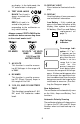
Section 1. Multimeter Basic Functions Digital multimeters or DMMs have many special features and functions. This section defines these features and functions, and explains how to use these functions to make various measurements. 1 11 5 10 3 2 8 7 4 9 6 Functions and Display Definitions 1. ROTARY SWITCH Switch is rotated to turn multimeter ON/OFF and select a function. ing the resistance of a component in an electrical circuit in the range of 0.1Ω to 20MΩ. (Ω is the electrical symbol for Ohms) 2.
on display. In the hold mode, the "H" annunciator is displayed. 10. DISPLAY LIGHT Press button to illuminate the display. 6. TEST LEAD JACKS BLACK Test Lead is always inserted in the COM jack. 11. DISPLAY Used to display all measurements and multimeter information. Low Battery – If this symbol appears in the lower left corner of the display, then replace the internal 9V battery. (See Fuse and Battery replacement on page 7.
Setting the Range Fig. 2 Two of the most commonly asked questions about digital multimeters are What does Range mean? and How do I know what Range the multimeter should be set to? Red What Does Range mean? Range refers to the largest value the multimeter can measure with the rotary switch in that position. If the multimeter is set to the 20V DC range, then the highest voltage the multimeter can measure is 20V in that range. Black the display.
Fig. 4 Fig. 5 Fig. 6 This sensor can’t be shorted so reduce the range setting until you get a value of resistance. ing or decreasing the number of digits after the decimal point. At the 200KΩ range the multimeter measured a value of 4.0. This means there is 4KΩ of resistance across the engine coolant sensor terminals. (See Fig. 4) Battery and Fuse Replacement Important: A 9 Volt battery must be installed before using the digital multimeter.
3. Remove screws from back of multimeter. negative (-) side of voltage source. 4. Remove back cover. NOTE: If you don’t know which side is positive (+) and which side is negative (-), then arbitrarily connect the RED test lead to one side and the BLACK to the other. The multimeter automatically senses polarity and will display a minus (-) sign when negative polarity is measured. If you switch the RED and BLACK test leads, positive polarity will now be indicated on the display.
1. Insert BLACK test lead into COM test lead jack. Fig. 9 2. Insert RED test lead into test lead jack. Unknown Resistance 3. Connect RED test lead to one side of voltage source. Black 4. Connect BLACK test lead to other side of voltage source. 5. Turn multimeter rotary switch to desired voltage range. Red 2. Insert BLACK test lead into COM test lead jack. If the approximate voltage is unknown, start at the largest voltage range and decrease to the appropriate range as required.
7. View reading on display - Note range setting for correct units. To measure DC Current (see Figs. 10 & 11): NOTE: 2KΩ = 2,000Ω; 2MΩ = 2,000,000Ω 1. Insert BLACK test lead into COM test lead jack. If you want to make precise resistance measurements, then subtract the test lead resistance found in Step 4 above from the display reading in Step 7. It is a good idea to do this for resistance measurements less than 10Ω. 2. Insert RED test lead into "10A" test lead jack or "mA" test lead jack. 3.
leads across diode and view display. Testing Diodes A diode is an electrical component that allows current to only flow in one direction. When a positive voltage, generally greater than 0.7V, is applied to the anode of a diode, the diode will turn on and allow current to flow. If this same voltage is applied to the cathode, the diode would remain off and no current would flow. Therefore, in order to test a diode, you must check it in both directions (i.e. anodeto-cathode, and cathode-to-anode).
Testing 1.5V, 9V and 12V Batteries Test Procedure (see Fig. 13): Fig. 13 Red Black Red Black 1. Insert BLACK test lead into COM test lead jack. 2. Insert RED test lead into test lead jack. 3. Turn multimeter rotary switch to 1.5V, 9V or 12V range. 4. Connect RED test lead to positive (+) terminal of battery. 5. Connect BLACK test lead to negative (-) terminal of battery. 6. View reading on display.
Section 2. Automotive Testing The digital multimeter is a very useful tool for trouble-shooting automotive electrical systems. This section describes how to use the digital multimeter to test the starting and charging system, ignition system, fuel system, and engine sensors. The digital multimeter can also be used for general testing of fuses, switches, solenoids, and relays. • If the reading is overrange Fuse is blown and needs to be replaced. NOTE: Always replace blown fuses with same type and rating.
• If the reading is overrange The switch is open. 6. View reading on display. • Typical solenoid / relay coil resistances are 200Ω or less. 7. Repeat Step 6 to verify switch operation. • Refer to vehicle service manual for the device's resistance range. If meter overranges, turn multimeter rotary switch to next higher range. (see Setting the Range on page 6) Testing Solenoids and Relays This test checks to see if a solenoid or relay has a broken coil.
Starting/Charging System Testing The starting system “turns over” the engine. It consists of the battery, starter motor, starter solenoid and/or relay, and associated wiring and connections. The charging system keeps the battery charged when the engine is running. This system consists of the alternator, voltage regulator, battery, and associated wiring and connections. The digital multimeter is a useful tool for checking the operation of these systems. No Load Battery Test 6.
Engine Off Battery Current Draw • Refer to vehicle service manual for manufacturers specific Engine Off Battery Current Draw. This test measures the amount of current being drawn from the battery when the ignition key and engine are both off. This test helps to identify possible sources of excessive battery current drain, which could eventually lead to a “dead” battery. NOTE: Radio station presets and clocks are accounted for in the 100mA typical current draw. 9. Test Results.
Cranking Voltage Battery Load Test 5. Connect BLACK test lead to negative (-) terminal of battery. This test checks the battery to see if it is delivering enough voltage to the starter motor under cranking conditions. 6. Turn multimeter rotary switch to 20V DC range. 7. Crank engine for 15 seconds continuously while observing display. Test Procedure (see Fig. 19): Fig. 19 8. Test Results. Compare display reading in Step 7 with chart below. Voltage Temperature 9.
Voltage Drops This test measures the voltage drop across wires, switches, cables, solenoids, and connections. With this test you can find excessive resistance in the starter system. This resistance restricts the amount of current that reaches the starter motor resulting in low battery load voltage and a slow cranking engine at starting. Test Procedure (see Fig. 20): 5. Turn multimeter rotary switch to 200mV DC range. 1. Disable ignition system so vehicle won’t start.
Component Voltage Battery Cable Connectors 50mV Connections 0.0V • Compare voltage readings in Step 6 with above chart. • If any voltages read high, inspect component and connection for defects. • If defects are found, service as necessary. Charging System Voltage Test 7. Turn off all accessories and view reading on display. This test checks the charging system to see if it charges the battery and provides power to the rest of the vehicles electrical systems (lights, fan, radio etc).
13. Test Results. • If voltage readings in Steps 7, 9, and 11 were as expected, then charging system is normal. • If any voltage readings in Steps 7, 9, and 11 were different then shown here or in vehicle service manual, then check for a loose alternator belt, defective regulator or alternator, poor connections, or open alternator field current. • Refer to vehicle service manual for further diagnosis.
Ignition System Testing The ignition system is responsible for providing the spark that ignites the fuel in the cylinder. Ignition system components that the digital multimeter can test are the primary and secondary ignition coil resistance, spark plug wire resistance and reluctance pick-up coil sensors. Ignition Coil Testing 7. Connect test leads. This test measures the resistance of the primary and secondary of an ignition coil.
Fig. 23 Secondary Coil Red Black Primary Coil Typical Cylindrical Ignition Coil manual for location of secondary ignition coil terminal. 16. Repeat test procedure for a HOT ignition coil. • Verify BLACK test lead is connected to primary ignition coil negative (-) terminal. NOTE: It is a good idea to test ignition coils when they are both hot and cold, because the resistance of the coil could change with temperature. This will also help in diagnosing intermittent ignition system problems. 13.
Ignition System Wires This test measures the resistance of spark plug and coil tower wires while they are being flexed. This test can be used for distributorless ignition systems (DIS) provided the system does not mount the ignition coil directly on the spark plug. Fig. 24 Black Red Spark Plug Wire Test Procedure: 1. Remove ignition system wires one at a time from engine. 3. Insert RED test lead into test lead jack. • Always grasp ignition system wires on the boot when removing. 4.
Magnetic Pick-Up Coils – Reluctance Sensors 5. Turn multimeter rotary switch to 2000 Ω range. Reluctance sensors are used whenever the vehicle computer needs to know speed and position of a rotating object. Reluctance sensors are commonly used in ignition systems to determine camshaft and crankshaft position so the vehicle computer knows the optimum time to fire the ignition coil(s) and turn on the fuel injectors. This test checks the reluctance sensor for an open or shorted coil.
Fuel System Testing The requirements for lower vehicle emissions has increased the need for more precise engine fuel control. Auto manufacturers began using electronically controlled carburetors in 1980 to meet emission requirements. Today’s modern vehicles use electronic fuel injection to precisely control fuel and further lower emissions. The digital multimeter can be used to measure fuel injector resistance. Measuring Fuel Injector Resistance Fuel injectors are similar to solenoids.
• This information is found in vehicle service manual. 8. Test Results Good Fuel Injector resistance: Resistance of fuel injector coil is within manufacturers specifications. Bad Fuel Injector resistance: Resistance of fuel injector coil is not within manufacturers specifications. NOTE: If resistance of fuel injector coil is within manufacturers specifications, the fuel injector could still be defective.
Testing Engine Sensors In the early 1980’s, computer controls were installed in vehicles to meet Federal Government regulations for lower emissions and better fuel economy. To do its job, a computer-controlled engine uses electronic sensors to find out what is happening in the engine. The job of the sensor is to take something the computer needs to know, such as engine temperature, and convert it to an electrical signal which the computer can understand.
• Thoroughly heat sensor tip as hot as possible, but not “glowing.” Sensor tip must be at 660°F to operate. 5. Test heater circuit. • If sensor contains 3 or more wires, then your vehicle uses a heated O 2 sensor. • Completely surround sensor tip with flame to deplete sensor of oxygen (Rich Condition). • Refer to vehicle service manual for location of heater pins. • Connect RED test lead to either heater pin. • Multimeter display should read... • Connect BLACK test lead to remaining heater pin.
• Oxygen Sensor output signal did not change when exposed to a rich and lean condition. 3. Insert RED test lead into test lead jack. 4. Disconnect wiring harness from sensor. • Oxygen sensor output voltage takes longer than 3 seconds to switch from a rich to a lean condition. 5. If testing Intake Air Temperature Sensor - Remove it from vehicle. All other temperature sensors can remain on vehicle for testing. Temperature Type Sensors 6. Connect RED test lead to either sensor pin.
Position Type Sensors range to get a more accurate reading. • • • • For all other temperature sensors: Start engine and let idle until upper radiator hose is warm. Turn ignition key OFF. Disconnect sensor wiring harness and reconnect multimeter test leads. View and record reading on display. Position sensors are potentiometers or a type of variable resistor. They are used by the computer to determine position and direction of movement of a mechanical device.
6. View and record reading on display. • Depending on hook-up, the display reading will either increase or decrease in resistance. • Display should read some resistance value. • The display reading should either start at or end at the approximate resistance value measured in Step 6. • If multimeter is overranging, adjust the range accordingly. (See Setting the Range on page 6.) • Some vane air flow sensors have an idle switch and an intake air temperature sensor in addition to a potentiometer.
Electrical Specifications DC Volts Range: 200mV, 2000mV, 20V, 200V Accuracy : ± (0.5% rdg + 2 dgts) Range: 500V Accuracy: ±(0.8% rdg + 2 dgts) AC Volts Range: 200V, 500V Accuracy : ± (1.2% rdg + 10 dgts) DC Current Range: 200µA Accuracy: ±(1.0% rdg + 2 dgts) Range: 200mA Accuracy: ±(1.2% rdg + 2 dgts) Range: 10A Accuracy: ±(2.0% rdg + 5 dgts) Resistance Range: 200Ω Accuracy: ±(0.8% rdg + 5 dgts) Range: 2000Ω, 20KΩ, 200KΩ Accuracy: ±(0.8% rdg + 2 dgts) Range: 20MΩ Accuracy: ±(1.