
User Manual


2
5. On some models, the hex nut adapter (Dia-
gram3) is pre-installed on the back of the
gauge. If not, install the hex nut adapter onto
the gauge.
6. Route the remaining tubing through the fire
wall to the gauge mounting location. Leave
at least one 3 or longer loop in the tubing
before it enters the fire wall and protect the
tubing from rough edges of the fire wall hole.
7. Repeat Step 3 to attach the tubing to the
gauge.
8. Complete the mounting of the gauge.
9. Refill the fluid level, if drained, to its normal
level.
10. Start the engine and observe the fitting con-
nections for leaks and the gauge for proper
operation.
For Electrical Gauges:
1. If you are mounting a fluid system, drain the
fluid level to a level below the warning light
sender location.
2. Remove the warning light sender from the en-
gine and insulate the end of the sender wire if
a T-Fitting is not being used. Install the
gauges sender in the same location in the
engine block. If an adapter is required, first
install the adapter and then the gauges
sender.
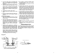
3. Optional T-Fitting (Diagram 2) - Install the
nipple into the T-Fitting and tighten the other
end of the nipple into the warning light sender
location in the engine block. Install an adapter
fitting first if needed. In one of the two remain-
ing openings in the T-Fitting, insert the gauge
sender. Insert the warning light into the re-
maining T-Fitting opening. Install the adapter
fitting first, if needed. (we do not produce
metric fittings for the connection from a met-
ric warning light sender to the T-Fitting).
4. Run a length of 18-gauge insulated copper
wire from the gauges sender to the gauges
mounting location.
5. Connect the wire to the connection on top of
the gauge sender.
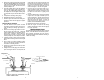
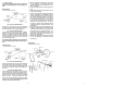
6. Facing the back of the gauge, the connection
post on the right is for +12 volts power, the
center post is for the ground connection and
left post is for the sender connection. After
you have mounted the gauge, connect the
sender wire to the left connection post as
shown in Diagram4. Do not over tighten.
7. Connect one end of another length of 18-
gauge insulated copper wire to the center con-
nection post, as shown in Diagram 4, and the
other end of the wire to a good ground source.
8. Connect a third length of 18-gauge insulated
copper wire to the right connection post as
shown in Diagram 4, and the other end of the
wire should be connected to the fuse box
where the wire will receive +12 volts of power
whenever the ignition key is in the START,
ON or ACCESSORY position.
9. Refill the fluid level, if drained, to its normal
level.
10. Start the engine and observe the fitting con-
nections for leaks and the gauge for proper
operation.
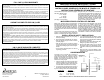
TROUBLESHOOTING
If your electrical gauge reads lower than you would
expect, check all electrical connections, particu-
larly grounding connections. Any poor connec-
tion will increase resistance resulting in a false
low reading.
CLOSED-EYE CONNECTOR
MAKE SURE CRIMP IS GOOD
GROMMET
U-BRACKET
NUT
WIRE
FLAT WASHER
NUT
WASHER
GAUGE
DO NOT LEAVE ANY HARDWARE
OUT OF THESE CONNECTIONS
Diagram 4
7