
User Manual


1
WATER/OIL TEMPERATURE GAUGE
INSTRUCTIONS
Warning: If your car is microprocessor (computer) controlled or has an electric cooling fan,
refer to the section on the front cover titled Microprocessor Controlled Engines.
6. Never install the captive fitting on the capil-
lary tube directly into the engine without an
adapter, as a proper seal will not be formed.
INSTALLATION
Note: If you are planning to use both an oil
temperature gauge and an an oil pressure
gauge, some modifications may be
necessary as there is only one available hole
for both senders. Since the temperature
gauge cannot use a T-fitting, we suggest that
you install the oil temperature sender into
the oil pressure warning light sender location
in the engine block. Then obtain an adapter
(which we do not manufacture) used for oil
coolers which will give you an additional outlet
for oil pressure.
FOR MECHANICAL GAUGES:
1. Drain the fluid level in the system to below the
senders mounting location which is normally
the factorys warning light sender location.
2. Route the capillary tubing through the mount-
ing hole for the gauge and then through the
firewall, protecting the tubing from rough
edges. Form at least one 3" or larger loop of
tubing as it comes through the firewall and
route the remainder to the sender mounting
locations.
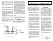
Temperature gauges measure the temperature
of any liquid their sender tip is submerged in. An
electrical temperature gauge is simpler and more
versatile for installation than a mechanical gauge
but is not quite as fast to respond to temperature
changes.
PRECAUTIONS
1. A temperature gauge requires that its sender
tip have a circulating flow around it to give an
accurate reading. For this reason, a T-fitting
cannot be used because it has no circulation
therefore the original warning light sender can-
not be operated off the same location. An ad-
ditional location may be available on the cyl-
inder head, intake manifold, or thermostat
housing but caution should be used in that
these locations may have different average
temperatures than the original warning light
sender location.
2. Do not over tighten the fittings or sender, par-
ticularly for mechanical gauges. The threads
are designed to strip before the engine com-
ponent can be damaged. The fittings use ta-
pered self-sealing threads and do not require
extreme force to seal properly.
3. Do not use sealing tapes or compounds on
electrical senders as this will disturb their
grounding connection to the engine resulting
in false low readings.
4. Take caution when uncoiling and routing the
mechanical gauges capillary tubing that you
do not bend it too sharply or flex it too often.
Any break in the inner tube will make the
gauge nonrepairable. A replacement service
is available only at the factory service center.
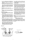
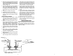
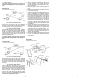
5. Always install the adapter fitting into the en-
gine first and then tighten the captive fitting
(Diagram1) on the capillary tube to avoid
twisting the tubing.
CAPILLARY
TUBE
Diagram 1
CAPILLARY TUBE TIP
CAPTIVE FITTING
INDICADORES DE TEMPERATURA DE AGUA/
ACEITE INSTRUCCIONES - TENSIÓN 12 V
THERMOM
È
TRE POUR EAU / HUILE -
INSTRUCTIONS
PARA NOMBRE, DOMICILIO Y TELEFONO DE IMPORTADOR: VER EMPAQUE.
8
ACTRON MANUFACTURING CO.
15825 Industrial Parkway
Cleveland, Ohio 44135
1-800-228-7667
©
2004 Actron Manufacturing Co.
All Rights Reserved.
0002-002-2403