® ST TE & LE ER DU EST MO R T N O TIO NS NI SE IG INE G EN H HIG FF W RO LO WE PO H RIC t lec Se W, LO TS L VO AN LE E NG RA S LT VO Y MS NC OH QUE E FR N TIO NC FU PU LS E PO WE R 9V . . ON . DS IGH LEA HT IS O H LL IG ET TA RL T NG EC HE RA NN OT ET CO AN N MO T: 1) S3) DIS AK IF M E ES S. . W CO Y T HM ON ER TO O T IS TT L H NA 9V BACTIONT LIG SIG UN ES TF TT SE OS 2) PM TO . IF O.
Vehicle Service Info The following publishers have manuals containing diagnostic information for electronic engine control and ignition systems. Contact the publishers for availability and pricing, specifying the make, model and year of your vehicle. Some manuals may be available at auto parts stores or your local public library.
Index Section 1 2 3 4 Vehicle Service Information ...................... Inside front cover Safety Precautions ............................................................... ii Tester Basics ............................................. 1-1 Testing Sensors .......................................... 2-1 • Troubleshooting Tips .......................................... 2-1 • Engine Coolant Temperature .............................. 2-2 • Inlet Air Temperature ..........................................
Safety First General Safety Guidelines to Follow When Working on Vehicles • Always wear approved eye protection • Always operate the vehicle in a well-ventilated area. Do not inhale exhaust gases – they are very poisonous! • Always keep yourself, tools, and test equipment away from all moving or hot engine parts. • Always make sure the vehicle is in Park (automatic transmission) or Neutral (manual transmission) and that the parking brake is firmly set. Block the drive wheels.
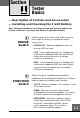
Section 1 Tester Basics — Description of Controls and Accessories — Installing and Checking the 9 Volt Battery Note: Detailed procedures for testing sensors and ignition modules are located in Section 2 (sensors) and Section 3 (ignition modules). 1 RANGE Switch Controls power to the Tester and selects measurement range sensitivity (as required by various sensor tests). • POWER OFF - No power supplied to either the tester or RED test lead. • LOW - Tester powered up for use.
Section 1 3 TEST Lights A single TEST light turns on to show the level of a measured signal (voltage, resistance or frequency). When signal values are low, the TEST light is off or near the bottom of the column. The TEST light moves higher up the column as the signal level increases. Sensor tests involve working the sensor and watching the TEST light move up, down or flash. Note that the motion of the light is more important than its actual position. 4 PULSE Light Used when testing ignition modules.
Tester Basics 6 IGNITION MODULE & ENGINE SENSOR TESTER TEST 3 HIGH 1 LOW POWER OFF 5 RICH RANGE Select LOW, VOLTS LEAN VOLTS 2 OHMS FREQUENCY FUNCTION PULSE 7 4 SIGNAL COMMON TRIGGER POWER 9V 9V BATTERY TEST: 1) SET RANGE TO HIGH. 2) SET FUNCTION TO OHMS. 3) DISCONNECT ALL LEADS. O.K. IF TOPMOST TEST LIGHT IS ON. WEAK IF ANOTHER LIGHT IS ON. 8 9 7 Backprobe Adapter To Sensor Allows test lead to probe sensor circuits when the sensor is connected to vehicle wiring harness.
Section 1 Tester Basics 8 Jumper Lead Used when checking some ignition modules. Makes extra connections as required for testing. 9 Connector Pin Adapters Used for easier attachment of test leads to certain sensor or wiring connector pins. • Push one end of the adapter onto the desired connector pin. • Grasp the other end with the test lead clip. Sensor Tester Power A 9-volt transistor radio battery must be installed to power the unit.
Section Section2 2 Troubleshooting Tips Testing Sensors Save yourself time! Always begin with a thorough visual and “hands-on” inspection. You can often find the cause of many problems by just looking. • Has the vehicle been serviced recently? Sometimes things get reconnected in the wrong place, or not at all. • Don’t take shortcuts. Inspect hoses and wiring which may be difficult to see due to location. • Inspect the air cleaner and ductwork for defects. • Check sensors and actuators for damage.
Section 2 Engine TEMPERATURE HIGH SENSOR RESISTANCE LOW Cold Typical Engine Coolant Temperature Sensor What is It? Hot TEMPERATURE The engine temperature sensor is a thermistor - a resister whose resistance changes with temperature. The hotter the sensor gets, the lower the resistance becomes. The thermistor is mounted inside the tip of a threaded metal housing. This is a 2-wire sensor. (Exception: some Chrysler engines have a dual sensor with three wires.
Air TEMPERATURE HIGH SENSOR RESISTANCE LOW Cold Typical Air Temperature Sensor What is It? Hot TEMPERATURE The air temperature sensor is a thermistor - a resister whose resistance changes with temperature. The hotter the sensor gets, the lower the resistance becomes. The thermistor is mounted inside the tip of a threaded metal housing. This is a 2-wire sensor. How is It Used? The computer needs to know air temperature to calculate the amount of air entering the engine.
Section 2 Testing Sensors Temperature Sensor Test Procedure Use this procedure for testing all engine coolant or inlet air temperature sensors. Exceptions: • Certain Toyota, Nissan and Ford engines using vane airflow sensors have the air temperature sensor built into the vane airflow assembly. Refer to page 2-40 for testing. • GM 1988 2.8L Mass Airflow Sensor (5 pin only) also has a built-in air temperature sensor. Use same test procedure as for vane airflow temperature sensor.
Engine Air TEMPERATURE 6) Verify test clips make good contact and do not touch each other. HIGH Make sure red and green test clips are not touching anything. LOW POWER OFF 7) Set RANGE switch to HIGH. RANGE VOLTS 8) Set FUNCTION switch to OHMS. OHMS FREQUENCY 9) Note TEST light position on tester. FUNCTION If the sensor is good, the light will move downwards as the sensor heats up. 10) On-Car test only: Disconnect test leads and reconnect sensor to vehicle wiring harness.
Section 2 Testing Sensors TYPICAL THROTTLE POSITION SENSORS HIGH What is It? Throttle Position Sensor SIGNAL The throttle position sensor is a VOLTAGE potentiometer - a type of variable resistor (similar to a dashboard dimmer control). These sensors come LOW in a wide variety of styles - some with MIN. MAX. ROTATION connectors at the end of a short wire “pigtail”. The computer supplies power and ground to the sensor. The sensor has an element which is turned (rotary type) or pushed (linear type).
THROTTLE POSITION Sensor/Switch • Sometimes a second switch is used to signal a wide open throttle condition. This switch is normally open (or closed - depends upon vehicle) when the throttle is at idle or just partially open. The switch operates when the throttle is opened beyond a certain point. (The amount of throttle opening required to operate the switch varies with vehicle.
Section 2 Testing Sensors Throttle Position Sensor Connectors A B = Test A, page 2-10 Some sensors require more than one test. = Test B, page 2-12 Note: If the Red and Black test lead hook-ups are reversed, the TEST light will move in the opposite direction during Test A. This does not affect the accuracy of the test or harm the sensor.
THROTTLE POSITION Sensor/Switch TOYOTA TOYOTA/NISSAN A B Red Yellow Black B Yellow Black B Yellow Black Not used on some vehicles. Perform this test only if vehicle Black Yellow mating connector has 3 wires. A Red Yellow Black Yellow B Some sensors have cable attached here. Testing is identical. Black Black Yellow Not used on some vehicles. Perform this test only if vehicle mating connector has 3 wires.
Section 2 Testing Sensors TEST A - Throttle Position Sensor Important: If more than one hook-up is shown, it means more than one test is required to check all parts of the sensor. Do all tests shown for your sensor. The letter next to the hook-up refers to the test procedure. Sensor may be tested on or off vehicle. (Exception: On-car test only for most Honda - sensor permanently attached to throttle body.) Warning: Observe all safety precautions (see page ii) if testing sensor on vehicle.
THROTTLE POSITION Sensor/Switch 7) Honda only: 1988-92 Civic and CRX – Remove vacuum hose from dashpot diaphragm. – Apply 20 in. Hg to the dashpot diaphragm using a hand vacuum pump. HIGH LOW – The dashpot diaphragm is part of the throttle body assembly. It is used to control cold engine fast idle and throttle closure speed so engine will not stall. POWER OFF RANGE VOLTS OHMS FREQUENCY FUNCTION 8) Set RANGE switch to HIGH. 9) Set FUNCTION switch to VOLTS.
Section 2 Testing Sensors TEST B - Throttle Position Switch Important: If more than one hook-up is shown, it means more than one test is required to check all parts of the switch. Do all tests shown for your switch. The letter next to the hook-up refers to the test procedure. Switch may be tested on or off vehicle. Warning: Observe all safety precautions (see page ii) if testing sensor on vehicle. 1) Verify ignition key is OFF. 2) Check Tester battery Refer to page 1-4.
THROTTLE POSITION Sensor/Switch HIGH LOW POWER OFF 7) Set RANGE switch to HIGH. RANGE VOLTS OHMS FREQUENCY 8) Set FUNCTION switch to OHMS. 9) Operate sensor - Watch TEST light for results. FUNCTION On-Car test: Slowly move throttle linkage back and forth from idle to wide open position. Off-Car test: Slowly rotate sensor element back and forth from end to end.
Section 2 Testing Sensors FORD EGR Valve What is it? HIGH SENSOR VOLTAGE LOW MIN. HONDA EGR Valve This sensor is a potentiometer - a type of variable resistor (similar to a dashboard light dimmer control). The computer supplies power and ground to the sensor. the sensor has a shaft which is pushed. When the sensor is mounted on the EGR valve, the shaft gets pushed as the valve opens. The sensor sends out a voltage signal indicating the amount of valve opening (“lift”).
EGR Valve Position/Lift Sensors EGR Valve Position Sensor Test Procedure Sensor may be tested on or off vehicle. Warning: Observe all safety precautions (see page ii) if testing sensor on vehicle. 1) Verify ignition key is OFF. 2) Check Tester battery Refer to page 1-4. Set RANGE switch to POWER OFF when done. 3) Disconnect wiring harness from sensor - Inspect for damage. Some vehicles use a metal snap ring to secure wiring harness to sensor. Remove this snap ring before disconnecting wiring harness.
Section 2 Testing Sensors Off-Car test: Slowly push sensor element back and forth from end to end. • Good Sensor - TEST light smoothly moves up or down as sensor is operated. (The TEST light may go off if it moves to the bottom of the column - this is O.K.) Range of TEST light movement varies with sensor type and vehicle mounting. • Bad Sensor - TEST light position does not change during test OR light movement is erratic, showing a sudden jump or dip during smooth sensor operation. 10) Testing is complete.
EGR Valve Position/Lift Sensors Sensor Connectors Note: If the Red and Black test lead hook-ups are reversed, the TEST light will move in the opposite direction during the test. This does not affect the accuracy of the test or harm the sensor. Black FORD Black Yellow Red HONDA – #1 HONDA – #2 Yellow Red Yellow Black Red Honda uses two sensor types. Try hook-up #1 first. If good test results are not obtained, retest using hook-up #2 before judging sensor.
Section 2 Testing Sensors Typical Oxygen Sensor What is It? The oxygen sensor is a zirconium dioxide ceramic mounted in the tip of a threaded metal housing. The tip is perforated to protect the sensing element but still allow exhaust gases to pass through. The sensor produces a voltage signal based on the amount of oxygen it contacts. A low voltage indicates a lean exhaust (too much oxygen). A higher voltage signals a rich exhaust (not enough oxygen).
OXYGEN HIGH SENSOR VOLTAGE LOW Lean OPTIMUM Rich AIR FUEL MIXTURE When to Test • Related trouble codes sent by computer. • Driveability problems such as rough running, hesitation, stumble, poor fuel economy, poor performance, black exhaust smoke. Inspection Sensor operation (see page 2-21). Poor connections at the sensor or computer. This sensor often fails because of contamination from fuel, oil additives, gasket sealer or an overly rich running engine.
Section 2 Testing Sensors Sensor Types 1-Wire: Single wire goes to sensor SIGNAL. Sensor housing is connected to sensor GROUND. 2-Wire: One wire goes to sensor SIGNAL. Second wire goes to sensor GROUND. Refer to vehicle service manual for wire identification. (Sensor wire is often black.) 3-Wire: Two wires (often the same color) go to the sensor heating element. Third wire (different color from the others) goes to sensor SIGNAL. Sensor housing is connected to sensor GROUND.
OXYGEN Heating Element Test • Do this test if sensor has a heating element (3 or 4 wire connector). • If sensor has 1 or 2 wire connector, do not do this test. Go directly to On-Car Test (page 2-22). Warning: Observe all safety precautions (see page ii) if testing sensor on vehicle. 1) Verify ignition key is OFF. 2) Check Tester battery Refer to page 1-4. Set RANGE switch to POWER OFF when done. 3) Disconnect wiring harness from sensor - Inspect for damage.
Section 2 Testing Sensors On-Car Test Important: Reliable testing of the oxygen sensor while on-vehicle is very difficult because test conditions cannot be well controlled. If the sensor responds during on-car testing, then it is probably good and no other testing is necessary. If the sensor does not seem to respond when tested on-car, remove it and perform the off-car test before deciding whether or not the sensor is bad. Warning: This test involves running the engine.
OXYGEN 8) Observe RICH/LEAN lights during fast idle. • The TEST light column also indicates sensor voltage, but it is easier to check operation by watching the RICH/ LEAN lights.) • Maintain throttle partially open (2000 RPM idle). – IF the RICH/LEAN lights flash back and forth every 3 seconds or less... THEN the sensor is good and no further testing is necessary. Go to step 10. – IF it takes longer than 3 seconds for the RICH/LEAN lights to switch back and forth... THEN the sensor may be degraded.
Section 2 Testing Sensors Off-Car Test Warning: This test involves use of an open flame from a propane torch. Observe all safety precautions for torch operation. Do not use near flammable material or gases. 1) Verify ignition key is OFF. 2) Check Tester battery Refer to page 1-4. Set RANGE switch to POWER OFF when done. 3) Disconnect wiring harness from sensor - Inspect for damage. Some vehicles use a metal snap ring to secure wiring harness to sensor.
OXYGEN 11) Observe RICH/LEAN lights while operating sensor. • After sensor tip is hot. move the flame until the sensor tip is completely surrounded by the flame. This keeps oxygen away from the tip. See Fig. 2. – Good Sensor: RICH light turns ON within 3 seconds indicating a “rich” (low oxygen) condition. – Bad Sensor: RICH light takes longer than 3 seconds to turn on, or does not turn on at all. • Move flame so oxygen can reach sensor tip. (Keep sensor tip hot with flame.) See Fig. 1.
Section 2 Testing Sensors Yellow Yellow Black Black What is It? The knock sensor is a piece of piezoelectric material mounted in a metal housing. The sensor acts like a microphone - it changes vibrations into a small AC voltage signal. The sensor usually has a one wire or two wire connector. How it is used? The computer (or other spark timing controller) is designed to recognize sensor signals caused by engine knock vibrations.
Engine KNOCK Knock Sensor Test Procedure Sensor may be tested on or off vehicle. Warning: Observe all safety precautions (see page ii) if testing sensor on vehicle. 1) Verify ignition key is OFF. 2) Check Tester battery (refer to page 1-4). 3) Disconnect wiring harness from sensor - Inspect for damage. 4) Connect test leads to sensor. One-wire connector: • YELLOW test lead to signal pin (top of sensor). • BLACK test lead to body of sensor (off-car) or nearby ground (on-car).
Section 2 Testing Sensors FORD GM/CHRYSLER TOYOTA/HONDA Manifold Absolute Pressure (MAP) Sensor Barometric Pressure (BARO) Sens What is It? How it is used? 2-28 This sensor is an electronic module which sends a signal to the computer indicating atmospheric pressure and/or engine vacuum. Depending upon sensor type, the signal may be a dc voltage or a frequency. More pressure (less vacuum) makes the sensor signal increase (higher voltage or frequency).
Manifold Absolute Pressure MAP/BARO The sensor is mounted either on the bulkhead, air cleaner, throttle body or elsewhere in the engine compartment. A vacuum hose connects the sensor to a strong source of manifold vacuum. (Some new MAP sensor types may be directly mounted to the manifold, eliminating the vacuum hose connection.) The BARO sensors are vented to the atmosphere there is no vacuum hose attached.
Section 2 Testing Sensors Manifold Absolute Pressure (MAP) Sensor Test Procedure Testing is done on-vehicle. Warning: This test involves running the engine. Observe all safety precautions (see page ii). Work in well-ventilated area. 1) Verify ignition key is OFF. 2) Check Tester battery Refer to page 1-4. Set RANGE switch to POWER OFF when done. 3) Connect test leads. Yellow Keep sensor connected to vehicle wiring. • YELLOW to sensor SIGNAL circuit. Use backprobe adapter. • BLACK to good vehicle GROUND.
Manifold Absolute Pressure MAP/BARO • Note: If the TEST light is OFF a problem exists. Go to step 9 and continue testing to find cause. 8) Operate sensor - Watch TEST light for results. (Note: Ignore any PULSE light action.) Non-Turbo Engines only: Start engine and let idle. Turbo Engines only: Attach hand vacuum pump to sensor vacuum port. Apply 18 in. vacuum. (More than 25 in. vacuum may damage sensor.) Good Sensor – TEST light moves downward during engine idle or when vacuum applied.
Section 2 Testing Sensors 11) Check MAP sensor power circuit. Keep sensor connected to vehicle wiring. HIGH LOW POWER OFF RANGE VOLTS OHMS • YELLOW test lead to sensor POWER circuit. Use backprobe adapter. • BLACK test lead to good vehicle GROUND. • RANGE on HIGH. • FUNCTION on VOLTS. FREQUENCY FUNCTION TEST • Ignition key ON. Good power circuit: Top (or next to top) TEST light ON. Go to next step. Bad power circuit: TEST light OFF or not in top (or next to top) position.
Manifold Absolute Pressure MAP/BARO 14) Check MAP signal wire for short to ground. HIGH LOW POWER OFF RANGE •Verify ignition key OFF and MAP sensor wiring harness disconnected. • RANGE on LOW. • FUNCTION on OHMS. VOLTS OHMS FREQUENCY FUNCTION • YELLOW test lead to MAP signal pin on vehicle harness connector. • BLACK test lead to good vehicle GROUND. Good circuit (no short): TEST light ON in any position. Go to next step. Bad circuit (shorted): TEST light OFF.
Section 2 Testing Sensors -F+ FLOW Typical MAF Sensor Mass Air Flow (MAF) Sensors What is It? This sensor is an electronic module which sends a signal to the computer indicating the amount of air entering the engine. Depending upon sensor type, the signal may be a dc voltage or a frequency. The signal level increases (higher voltage or frequency) as the air flow increases. Within the sensor is a heated wire located in the path of incoming air.
Mass Air Flow MAF Vehicle Harness Connectors for MAF Sensor (Mating side of connector shown.) GM MAT SIGNAL MAT RTN POWER GROUND MAF SIGNAL POWER MAF SIGNAL GROUND 1988 and Older RANGE on LOW FUNCTION on FREQUENCY 1988 2.8L only RANGE on LOW FUNCTION on FREQUENCY GROUND MAF RETURN MAF SIGNAL BURN-OFF SIGNAL POWER POWER GROUND MAF SIGNAL 1989 and Newer RANGE on HIGH FUNCTION on FREQUENCY Ford NOTE: MAF RETURN is not connected to vehicle GROUND. All 5-Pin except 1988 2.
Section 2 Testing Sensors Vehicle Harness Connectors for MAF Sensor (Mating side of connector shown.
Mass Air Flow MAF Mass Air Flow (MAF) Sensor Test Procedure Testing is done on-vehicle. Warning: This test involves running the engine. Observe all safety precautions (see page ii). Work in well-ventilated area. 1) Verify ignition key is OFF. 2) Check Tester battery Refer to page 1-4. Set RANGE switch to POWER OFF when done. 3) Connect test leads - refer to hook-up diagram. Keep sensor connected to vehicle wiring. • YELLOW to sensor SIGNAL circuit. Use backprobe adapter. • BLACK to good vehicle GROUND.
Section 2 Testing Sensors – Note: If test results are O.K. but a computer trouble code indicates a bad sensor signal, the wire between the sensor signal pin and the computer may be open. – Testing is complete. Problem exists (Bad sensor or wiring): – TEST light position does not change during test. – Go to step 9 and continue testing to find cause. Do all steps to avoid replacing a good sensor! – Note: Sensor is defective if TEST light jumps erratically when sensor GENTLY tapped with lightweight tool.
Mass Air Flow MAF 12) Check MAF sensor ground circuit. • Same set-up as previous step, but move YELLOW test lead to sensor GROUND circuit. Do not probe MAF RETURN pin. Use backprobe adapter. Good ground circuit: TEST light OFF. Go to next step. Bad ground circuit: Any TEST light ON. Repair open in ground circuit wiring, then retest. 13) Check for connector problems. • Ignition key OFF. • Disconnect wiring harness from MAF sensor. (Some vehicles use a metal snap ring to secure wiring harness to sensor.
Section 2 Testing Sensors Typical VAF Sensor AIR FLOW Referred to as Vane Air Flow (VAF) sensor or Air Flow Meter Vane Air Flow Sensors What is It? How it is used? Location When to Test What to Inspect 2-40 This sensor sends a dc voltage signal to the computer indicating the amount of air entering the engine. The voltage signal increases as the air flow increases. The sensor assembly has a pivoting door (“vane”) which is opened by incoming air.
Vane Air Flow VAF Sensor Connectors Toyota 1 2 3 4 5 Red Black 7 A* Yellow Black 1 6 #1 2 3 4 5 Red 6 7 Yellow *Toyota uses two sensor types. Try hook-up #1 first. If good test results are not obtained, retest using hook-up #2 before judging sensor. A* 1 2 3 Black 1 4 5 6 7 B Yellow 2 3 4 5 6 7 Black Yellow C #2 Nissan A* #1 Black Red *Nissan uses two sensor types. Try hook-up #1 first.
Section 2 Testing Sensors TEST PREPARATION: All Air Flow Meter Sensor Tests IMPORTANT: • Test all hook-ups shown for the sensor. • The letter next to the hook-up refers to the test procedure for that hook-up. • Each hook-up should test O.K. Exception: If two hook-ups are marked with an asterisk (*) only one of the two hook-ups has to test O.K. This is necessary because some sensors look alike, but have different internal connections. Sensor may be tested on or off vehicle.
Mass Air Flow MAF TEST A - Air Flow Meter Sensor Warning: Observe all safety precautions (see page ii) if testing sensor on vehicle. 1) Do all Test Preparation steps. Refer to page 2-42. 2) Connect test leads. • Connect TEST leads according to diagram A in the component drawing. • Important: If two hook-ups are marked with an asterisk (*) only one of the two hook-ups has to test O.K. This is necessary because some sensors look alike, but have different internal connections.
Section 2 Testing Sensors TEST B - Air Temperature Sensor Warning: Observe all safety precautions (see page ii) if testing sensor on vehicle. 1) Do all Test Preparation steps. Refer to page 2-42. 2) Connect test leads. Connect TEST leads according to diagram B in the component drawing. 3) Verify test clips make good contact and do not touch each other. HIGH LOW Make sure unused clips are not touching anything. POWER OFF RANGE VOLTS OHMS 4) Set RANGE switch to HIGH. 5) Set FUNCTION switch to OHMS.
Mass Air Flow MAF Test C - Air Flow Meter Position Switch Warning: Observe all safety precautions (see page ii) if testing sensor on vehicle. 1) Do all Test Preparation steps. Refer to page 2-42. 2) Connect test leads. Connect TEST leads according to diagram C in the component drawing. 3) Verify test clips make good contact and do not touch each other. HIGH LOW POWER OFF RANGE VOLTS Make sure unused clips are not touching anything. 4) Set RANGE switch to HIGH. 5) Set FUNCTION switch to OHMS.
Section 2 Testing Sensors Wire Coil Tooth Reluctor Ring Magnet To Computer S SENSOR VOLTAGE N Rotation Air Gap Reluctance Sensor Operation Positive Zero Negative ROTATION Typical Sensor Signal Voltage Crankshaft/Camshaft Position sensors What is It and How is It Used? — The computer needs to know rotational speed (or position) of the engine crankshaft/camshaft for controlling ignition and fuel injector systems.
Crankshaft/Camshaft Position HIGH SHUTTER POWER SIGNAL VOLTAGE HALL SWITCH MAGNET GROUND LOW SIGNAL ROTATION Typical Hall Effect Sensor Typical Sensor Signal Voltage The computer determines rotational speed (or position) by measuring how fast (or when) pulses appear. Note: The voltage pulses get larger when the teeth pass by more quickly. Values can range from a fraction of a volt (crank RPM) to over a hundred volts (high RPM).
Section 2 Testing Sensors Where is It? — Crankshaft Position, Crank Angle, Flywheel, Distributor Pick-Up, Camshaft Position, Cylinder, TDC and RPM. The sensor is usually located inside the distributor (if the engine has one). Vehicles without a distributor have the sensor located in various places around the engine where it can be mechanically linked to the crankshaft or camshaft. — Driveshaft: Sensor located in transmission housing or near driveshaft.
Crankshaft/Camshaft Position Test A - Magnetic Reluctance Type Sensor Testing is done on-vehicle. DO NOT test vehicle speed or driveshaft type sensors since they require vehicle motion. Warning: Observe all safety precautions (see page ii) when testing sensor on vehicle. 1) Verify ignition key is OFF. 2) Check Tester battery Refer to page 1-4. Set RANGE switch to POWER OFF when done. 3) Disconnect wiring harness from sensor - Inspect for damage.
Section 2 Testing Sensors Observe all safety precautions (see page ii) - engine may start or backfire. Note: Some computer systems will store a trouble code in memory (and turn on the “Check Engine” light) if engine is cranked with sensor disconnected. Ignore or erase the code after testing. Refer to vehicle service manual. TEST – Wheel Speed sensor: Raise wheel off ground. Use jack stands and observe all safety precautions (see page ii). Give the wheel a quick spin in either direction to test.
Crankshaft/Camshaft Position Test B - Hall Effect Type or Optical Type Sensor Sensor may be tested on or off vehicle. Warning: Observe all safety precautions (see page ii) if testing sensor on vehicle. 1) Verify ignition key is OFF. 2) Check Tester battery Refer to page 1-4. Set RANGE switch to POWER OFF when done. 3) Disconnect wiring harness from sensor - Inspect for damage. Some vehicles use a metal snap ring to secure wiring harness to sensor. Remove this snap ring before disconnecting wiring harness.
Section 2 Testing Sensors On-Car test: Crank engine. STAY AWAY from moving engine parts. Observe all safety precautions (see page ii) - engine may start or backfire. PULSE Good sensor - PULSE light flashes or stays ON during cranking (varies with sensor type). Bad sensor - PULSE light OFF during cranking. Note: Some computer systems will store a trouble code in memory (and turn on the “Check Engine” light) if engine is cranked with sensor disconnected. Ignore or erase the code after testing.
Section Section2 3 Troubleshooting Tips Testing Ignition Modules Save yourself time! Always begin with a thorough visual and “hands-on” inspection. You can often find the cause of many problems by just looking. Has the vehicle been serviced recently? Sometimes things get reconnected to the wrong place, or not at all. Poor grounding can cause no-starts! Some modules make ground connections to vehicle chassis.
Section 3 Testing Ignition Modules Ignition Module Test Procedure GM • Ford • Chrysler • Toyota • Honda • Nissan Important: • This test checks for “dead” modules causing a no-start. This test will not detect intermittent failures due to heat or engine vibration. • Refer to vehicle service manual for module location, removal and installation procedures. – Module access may require distributor removal.
IGNITION MODULES GM 7 & 8 pin modules only: – Reconnect test leads as shown in Test 2 diagram. – Observe PULSE light. It should NOT be flashing. If PULSE light flashes, module is bad. – Short pins E and R together using paper clip (or other metal jumper). – Observe PULSE light for test results. • Flashing light means good module. (There may be a short delay before flashing starts.) • No flashing means bad module. Ford modules with two test hook-ups: – Reconnect test leads as shown for Test 2.
Section 3 Testing Ignition Modules GM 4 and 5 pin Black * Yellow Red Green * Test clip must touch both base plate and bushing BUSHING BASE PLATE Black * Yellow Red 3-4 Green
GM 7 pin Test 1 Black Black * * Yellow Red Green Yellow Green Red Test 2 Black * * Test clip must touch both base plate and bushing BUSHING BASE PLATE Black Yellow Green Red Blue Jumper * Yellow Red Green Blue Jumper 3-5
Section 3 Testing Ignition Modules GM 8 pin Green P N Test 1 +C SIDE VIEW GBRE C Red G B R END VIEW E Black Yellow Green P N Test 2 +C Red GBRE C G R E Black Yellow 3-6 B Blue Jumper SIDE VIEW END VIEW
Ford Dura-Spark Blue Jumper Red White Red Black Black (or Black/Green) MODULE Yellow Green Green Orange Note: Dura-Spark ignition modules come in several versions with different connector types. Make connections based on ignition module wire colors. Other module wires not used for testing.
Section 3 Testing Ignition Modules Ford TFI-IV Black Test 1: Connect leads as shown. Test 2: Move Green lead to pin 5. Other leads remain in original position Green 7 8 9 6 5 4 3 2 1 Red Yellow SIDE VIEW END VIEW Ford TFI-IV Test 1: Connect leads as shown. Test 2: Move Green lead to pin 5.
Chrysler 4 and 5 pin 5-pin type shown. 4-pin uses same hook-up.
Section 3 Testing Ignition Modules Honda 1 2 3 4 Black Green Red Yellow Red Red Green Yellow 3 2 Green Yellow 1 3 2 1 4 4 Black 3-10 Connect BLACK test lead to igniter mounting holes or a metal ground inside distributor.
Honda/Nissan Yellow C B Red Bushing Green Base plate I W Black Not present on some modules. Test clip must touch both base plate and bushing IMPORTANT Red 1) Remove distributor from engine before testing. 2) Module remains inside distributor during test. Yellow Black Red Yellow Connect BLACK test lead to a good ground inside distributor. Black E Red Yellow B I Connect BLACK test lead to a good ground inside distributor.
Section 3 Testing Ignition Modules Nissan Test clip must touch both base plate and bushing Bushing Base plate S B I E Black Yellow Pick-up pins Green Red Nissan One-Coil System (Photo pick-up) * 1987-1989 300ZX only Nissan uses two types of connector wiring. Module is good if either hook-up tests O.K.
Nissan Two-Coil System (Photo pick-up) Yellow * Green Black Nissan uses two types of connector wiring. Module is good if either hook-up tests O.K. * Green * Yellow 1 4 2 3 OR Black Black 1 4 2 3 Green Yellow Green Yellow Black Not present on some modules.
Section 3 Testing Ignition Modules Toyota Yellow Use a paper clip to connect test lead. Red Green Black Connect BLACK test lead to igniter mounting hole or good vehicle ground.
Toyota Green Red BROWN BLACK Yellow Black Connect BLACK test lead to igniter mounting hole or good vehicle ground.
Section 3 Testing Ignition Modules Toyota Green Red Yellow Yellow Use a paper clip to connect test lead. Black Connect BLACK test lead to igniter mounting hole or good vehicle ground.
Toyota Green Black Connect BLACK test lead to igniter mounting hole or good vehicle ground. Red Yellow Use a paper clip to connect test lead.
Section 3 Testing Ignition Modules Toyota Black Connect BLACK test lead to igniter mounting hole or good vehicle ground. Green Red Yellow Use a paper clip to connect test leads.
Toyota Yellow Red Green Green Yellow Red Black Connect BLACK test lead to igniter mounting hole or good vehicle ground.
Section 3 Testing Ignition Modules Toyota Yellow Red Green Black Connect BLACK test lead to igniter mounting hole or good vehicle ground.
Toyota Red Red Green Green B + SG + B SG C C Yellow Yellow Red Green B C Red Yellow T F Yellow T F B C Green Connect BLACK test lead to igniter mounting holes.
Notes 3-22
Section Section2 4 More Uses for the Ignition Module & Engine Sensor Tester Circuit Voltage Checks This function is useful for checking the presence (or absence) of voltages throughout the vehicle electrical system (such as wiring, switches, relays, and connectors). It is safe for probing computer and sensor circuits. Warning: Observe all safety precautions when working on vehicles (see page ii). HIGH LOW POWER OFF 1) Set FUNCTION switch to VOLTS. RANGE VOLTS OHMS FREQUENCY FUNCTION VOLTS over5 4.
Section 4 Continuity Checks Test wiring, ground connections, switch operation, relay contacts, or similar. Important: • Do continuity tests on unpowered circuits only. • Always make sure all connections are good. If necessary, scrape away corrosion, paint, etc. at the contact points. Warning: If working on-car, turn ignition key OFF and observe all safety precautions (see page ii). HIGH LOW 1) Set RANGE switch to HIGH. POWER OFF 2) Set FUNCTION switch to OHMS.
More Uses for the Ignition Module/Sensor Tester Continuity Checks (cont.
Section 4 Diode Checks Tests diodes and rectifiers for proper operation. HIGH LOW POWER OFF RANGE 1) Set RANGE switch to HIGH. 2) Set FUNCTION switch to OHMS. VOLTS OHMS FREQUENCY 3) Connect TEST leads as shown in Figure 1. ( YELLOW to anode — BLACK to cathode) FUNCTION 4) The bottom TEST light should be ON. If a different TEST light is on or all lights are off, the diode is defective. 5) Reverse test lead connections as shown in Figure 2.
Warranty (Garantia) FULL ONE (1) YEAR WARRANTY Actron Manufacturing Company, 9999 Walford Avenue, Cleveland, Ohio 441024621, USA warrants to the user that this unit will be free of defects in materials and workmanship for a period of one (1) year from the date of original purchase. Any unit that fails within this period will be repaired without charge when returned to an authorized factory repair center.
® Made in the U.S.A. Actron Manufacturing Company 9999 Walford Avenue Cleveland, Ohio 44102-4696 ©1997, Actron Manufacturing Company Part No.