
User Manual
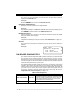
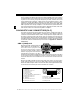
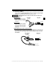

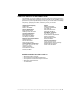

Table Of Contents
- Safety Precautions
- Getting Started
- Using The Tool
- Global OBD II Diagnostics
- GM Historic Diagnostics
- Ford Historic Diagnostics
- Chrysler Historic Diagnostics
- Help & Troubleshooting

Getting Started • • • • • • • • • • • • • • • • • • • • • • • • • • • • • • • • • • • • • • • • • • • • • • • • • • • • • • • •
1 – 4 • • • • • • • • • • • • • • • • • • • • • • • • • • • • • • • • • • • • • • • • • • • • • • • • • • • • • • • • •
1
SAE publishes recommendations, not laws, but the Environmental Protection
Agency (EPA) and California Air Resources Board (CARB) made many of SAE’s
recommendations legal requirements that vehicle manufacturers were required
to phase in over a three-year period. Beginning in 1994, vehicles with a new
engine management computer – about 10% of each manufacturers fleet – were
supposed to comply with OBD II standards. For 1995, OBD II systems were to
appear on about 40% of the new vehicles sold in the USA. Some of the 1994-1995
OBD II systems were not fully compliant, so the Government granted waivers to
give manufacturers time to fine-tune their systems. Beginning in 1996, most of the
new vehicles sold in the USA were fully OBD II compliant.
DIAGNOSTIC LINK CONNECTORS (DLC)
The Data Link Connector (DLC) allows the scan tool to communicate with the
vehicle’s computer(s). Before OBD II, manufacturers used different data link
connectors to communicate with the vehicle. The proper DLC adapter cable must
be used to connect the tool to the vehicle. Also, the vehicle’s DLC may be found
in several different places and have many different configurations. The following
describes the DLCs used by Ford, GM and Chrysler. The DLC location and types
for domestic vehicles can be looked up in the charts in “Appendix A – Data Link
Connectors” .
OBD II (J1962) DLC
Beginning in 1996, vehicles sold in the
United States use the J1962 DLC, a
term taken from a physical and
electrical specification number
assigned by SAE (J1962). OBD II
defines the physical and electrical
specification for the DLC. The DLC
should be located under the dashboard on the driver side of the vehicle. If the DLC
is not located under the dashboard as stated, a decal describing its location
should be attached to the dashboard in the area the DLC should have been
located.
Because the OBD II J1962 connector has power and ground, you only need a
single cable connection to the tool for both power and tool communications.
Attach the OBD II adapter cable to the extender cable, both supplied with the tool,
to connect the tool. Certain pins in the connector are reserved.
1 - Manufacturer Reserved
2 - J1850 Bus+
3 - Manufacturer Reserved
4 - Chassis Ground
5 - Signal Ground
6 - CAN High, J-2284
7 - K Line, ISO 9141-2 & ISO/DIS 14230-4
8 - Manufacturer Reserved
9 - Manufacturer Reserved
10 - J1850 Bus
11 - Manufacturer Reserved
12 - Manufacturer Reserved
13 - Manufacturer Reserved
14 - CAN Low, J-2284
15 - L Line, ISO 9141-2 & ISO/DIS 14230-4
16 - Battery Power
1
9
8
16