
User Manual
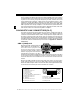
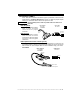

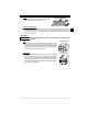

Table Of Contents
- Safety Precautions
- Getting Started
- Using The Tool
- Global OBD II Diagnostics
- GM Historic Diagnostics
- Ford Historic Diagnostics
- Chrysler Historic Diagnostics
- Help & Troubleshooting

• • • • • • • • • • • • • • • • • • • • • • • • • • • • • • • • • • • • • • • • • • • • • • • • • • • • • • • • • 1 – 5
• • • • • • • • • • • • • • • • • • • • • • • • • • • • • • • • • • • • • • • • • • • • • • • • • • • • • • • • Getting Started
1
Ford Historic (OBD I)
Since 1984, Ford used several different types of powertrain control modules
(PCM). Refer to “On-Board Diagnostics” on page 1-2. With the proper adapter
cables, your tool will be able to read these systems as well.
Use the Battery Power cable to provide 12V to the tool for all
systems.
EEC-IV System
The EEC-IV computer system
uses a large six-sided
connector and a pigtail
connector.
MCU System
The MCU computer system
uses the same six-sided
connector, but NOT the pigtail
connector. Leave the pigtail
unattached.
MECS (Mazda Electronic Control System)
MECS vehicles (1988 –1995) use either a 6-pin (with pigtail) or a 17-pin DLC. The
6-pin MECS adapter cable and jumper wires (P/N 9131) are used to connect the
tool to both DLCs. Both adapter cables are also available through your dealer.
6-Pin MECS.
IMPORTANT
Vehicle DLC
EEC-IV/MCU
Cable Adapter
EEC-IV/MCU
STI Pigtai
l
EEC-IV onl
y
To Scan
Tool
P/N CP9128
STI Pigtail
4
5
6
1
2
3
To Scan
Too l
6-Pin MECS
Clip to good
Vehicle ground
Cable Adapter
Vehicle DLC
6-Pin MECS
Pigtail
P/N CP9131